# 5G Outdoor CPE Router
Utilizing the latest 5G technology, the 5G outdoor CPE router delivers fast internet speeds to provide high-speed broadband connectivity.
Designed for outdoor 5G WiFi internet, the 5G CPE receives the best outdoor 5G mobile signals and provides large-scale wireless internet coverage. The waterproof enclosure allows you to use it in rugged applications and challenging environments. Here is the basic working principle diagram.
For more product details, especially the features and specifications, please visit our website at [www.OutdoorRouter.com](https://www.outdoorrouter.com/).
|
| Computer: | Windows / Mac / Linux / etc |
# 1.1 Package Contents
After receiving the package, please check if all components below are included.
Open the box from the **openside**. Below contents are in the first layer with a black sponge.
1 x 5G Outdoor CPE Router\
3 x Omni FRP 5G Antenna\
2 x Omni FRP WiFi Antenna
Take out the router and antenna, and pull out the black sponge from the central rhombic hole.\
You will find the items below in a black clamshell.
1 x 10-meter LAN Cable\
1 x PoE Injector\
1 x L-Shape bracket\
2 x U-Bolts with holders\
1 x T-shape wrench
EZR34T-5G Package Contents
{% hint style="info" %}
Please keep the original package for a few weeks. You can also use the rugged 5-layer corrugated box to store the other devices.
{% endhint %}
# 1.2 Interface Overview
The EZR34T-5G CPE router has 5x antenna sockets, 1x gland socket, 1x breather valve, and 1x lock hole, as shown below.
All of the antenna sockets are N-female type. 5G mobile antenna sockets are on the top side, and Wi-Fi antenna sockets are on the bottom.
*Port numbers **\[1\~6]** are embossed on the enclosure.*
EZR34T-5G Interface Overview
There are two types of ends on the T-shape wrench.
The hexagon end fits the hexagon bolts on the lid. The cross end is fit to cross-headed screws on the backside. Use one of the Hexagon ends on the wrench and turn in an anti-clockwise direction to lose the bolts on the lid. Then we can open the enclosure.
# 1.3 Install Antennas
You can install the antennas after finishing the below step 2 or step 3.
The 5G mobile antennas are marked MOBILE, and Wi-Fi antennas are engraved WIFI4-5.
Locate the antenna sockets on the enclosure. There are six embossed numbers on the top & bottom sides. 1-2-3 are for MOBILE antennas 4 & 6 are for WIFI4-5 antennas.
Put antennas aligned at corresponding sockets, and turn the milled part on the antenna head clockwise to tighten them.
EZR34T-5G - Install Mobile WiFi Antennas
{% hint style="info" %}
While installing the antenna, put the router device in a vertical or horizontal direction to avoid bending the pins in the antenna connector.
The default Omni antennas are polarized vertically. Please always use the antenna in a vertical direction.
{% endhint %}
### Upgrade Antennas
All of the antenna base connectors are N-female type.
If the RSRP signal strength is below -100 dBm, suggest upgrading the 5G antennas to directional antennas to improve the signal reception. If using the router in an RV or boat, please upgrade to FRP or MIMO Omni antennas.
Ensure your antennas are with N-Male connectors and working on the correct frequency range. If you connect antennas with extra coaxial cables, suggest using cable lengths shorter than 5 meters to reduce the RF signal attenuation.
# SIM Card & PoE
Open the enclosure and continue the initial settings.
{% content-ref url="/pages/pUMP3SMbwVo25nwVmNQi" %}
[2.1 Insert SIM Card](/manual/sim-card-and-poe/2.1-insert-sim-card)
{% endcontent-ref %}
{% content-ref url="/pages/Bx4Kz7j0T5DhANgenR1t" %}
[2.2 PoE Connection](/manual/sim-card-and-poe/2.2-poe-connection)
{% endcontent-ref %}
{% content-ref url="/pages/VDOtMaXC9iMrhvLJAETE" %}
[2.3 Indicators](/manual/sim-card-and-poe/2.3-indicators)
{% endcontent-ref %}
***
On the bottom side of the motherboard, there are the Reset button, Indicators, WAN, LAN, and DC socket as the below image shows. The SIM card slots are in the top right corner.
EZR34T-5G - Internal Motherboard Interfaces
# 2.1 Insert SIM Card
Use a Nano SIM card (12.3x8.8mm) in the router. If it's a new SIM card, please follow the instruction from the mobile carrier to activate the SIM card.
{% hint style="warning" %}
Please always **turn off the power** while inserting or removing the SIM card.\
Please use an unlocked and activated SIM card.
{% endhint %}
### **Insert A SIM Card**
1. Locate the SIM1-2 slots in the top right corner of the motherboard.
2. Hold the lid of the SIM card slot and slide left to open the cover.
3. Put a Nano SIM card in the **SIM1** slot. \
*There is only one correct way to settle the SIM card - the gold pins should be face down, and the notch should be on the top right corner.*
4. Cover the SIM lid and slide right to lock the lid.
EZR34T-5G - Insert Nano SIM Card in SIM1 Slot
{% hint style="info" %}
**Clean the SIM Card**
please check if the SIM card is clean, especially on the golden contacts. If there is dust/dirt/oil on the SIM card, you can follow the tips to [clean the SIM card](https://www.outdoorrouter.com/outdoor-4g-router-with-sim-card-slot/).
{% endhint %}
# 2.2 PoE Connection
Complying with 802.3af/at PoE standard, the router uses a LAN cable to transmit 52Volt DC power and 1Gbps Ethernet data. A 52Volt 802.3at standard PoE injector and 10-meter outdoor-grade LAN cable are included in the package.

You can use a max 50-meter LAN cable. Suggest using CAT6 or higher-grade LAN cable and ensure it's the TIA/EIA568B wiring. Please refer to the below image.
EZR34T-5G CPE - PoE Connection
## **Connect to PoE Injector**
Refer to the above sketch and follow the below steps to connect the router to the PoE injector.
1. **Take apart the PoE gland.**\
Turn the white color cap off from the gland in an anti-clockwise direction.\
Then push out the orange color stopper from the inside direction of the barrel connector.
2. **Take one end of the LAN cable through the cap.**
3. **Put the LAN cable through the barrel screw** and plug in the PoE & LAN port on the motherboard.
4. **Clamp the stopper on the LAN cable** and settle it in the barrel.\
\* The smaller end of the orange color stopper should face the outside.
5. **Turn the cap clockwise** to tighten it on the barrel screw.
6. Connect another end of the LAN cable **to the PoE port on the PoE injector**.
7. Connect the AC plug on the PoE injector to an electrical outlet after finishing all the hardware installation.
{% hint style="info" %}
#### LAN Cable Distance
There will be a distinct attenuation on the Ethernet signal when the LAN cable is longer than 50 meters. You can use a PoE extender to boost the signals, then use a longer-distance LAN cable.
{% endhint %}
## PoE Ethernet Connection
The PoE injector has two RJ45 ports, PoE and LAN.\
The PoE port outputs 52Volt 0.5Amps DC power to boot up the router.
**Router Mode --** When the PoE port links to the LAN port on the router, the LAN port on the PoE injector outputs Ethernet from the router. You can connect the LAN port to a computer or another router or switch to extend the mobile internet network system.
**Extender Mode --** When the PoE port links to the WAN port on the outdoor router, the LAN port on the PoE injector acts as the WAN port to input the Internet to the outdoor router. Connect the LAN port on the PoE injector to another internet router, and the outdoor router will work as an extender.
## Alternative Power Sources
### i. PoE Switch
You can replace the default PoE injector with an IEEE802.3at standard PoE switch. On an unmanaged switch, the other terminals linked to the same switch can obtain Internet from the outdoor router.
### ii. 12Volt Power
The DC socket on the outdoor router takes wide range DC power, 9\~52 Volt. The DC socket supports a standard Ø5.5/2.1mm DC plug. The PoE gland can take an extra DC power cable.
If both the DC socket and PoE power are enabled, the router will use the firstly connected power source. If one of them drops, the router will switch to another power source seamlessly.
{% hint style="danger" %}
Do not use an overloaded electrical current on the DC socket! \
The suggested typical DC power is 12Volt 1\~2Amps.
{% endhint %}
# 2.3 Indicators
There are eight indicators on the EZR34T router.
The SIM card indicators are in the top left corner of each SIM card slot. They will turn on when a related SIM slot is activated.
On the bottom side of the motherboard are Wi-Fi, System, Mobile, Power, WAN, and LAN indicators, as the image below shows.
EZR34T-5G Onboard Indicators
Indicator
Status
Description
Indicator
Status
Description
SIM Card
Green
Turns on when a related SIM slot is activated.
Power
Green
Turns on when connected to PoE or DC power source.
System
Green
This light indicates that the router is in operation. If it lit solid green, then the router has booted successfully.
Flash
The router system is booting up. The system indicator flashes while resetting or flashing the firmware.
Off
Short of power. Check the PoE or DC power connection.
Wi-Fi
Green
Wi-Fi hotspot is enabled. You can find and connect to the Wi-Fi hotspot if the light is green.
Flash
If you are connected to the Wi-Fi hotspot, it will flash green to indicate data going to and from the router. If the router is connected to another Wi-Fi hotspot (Wi-Fi relay), it will also flash because it has the data flow.
Off
If it's off, your router no longer sends a Wi-Fi signal. You can log in to the router admin and turn on the Wi-Fi hotspot.
Mobile
Green
Indicates the router is using a SIM card.
Flash
Means mobile internet is activated with data flow.
Off
No workable SIM card or Mobile interface is stopped.
# Bracket & Mounting
The outdoor router has a patented waterproof enclosure and white weather-proof coating for work in demanding environments.
{% content-ref url="/pages/JsCXEEmxPXF3J23sgaTe" %}
[3.1 Signal Coverage](/manual/bracket-and-mounting/3.1-signal-coverage)
{% endcontent-ref %}
{% content-ref url="/pages/1HhT01Qipw9u7f3IERMV" %}
[3.2 Install On A Pole](/manual/bracket-and-mounting/3.2-install-on-a-pole)
{% endcontent-ref %}
***
The waterproof enclosure is diecast from anti-corrosion ADC12 aluminum by 100-ton pressure. It's passed a bundle of rugged tests for long-period outdoor operation, such as the Salt Spray Test, Leakage Test, IP67 Waterproof Test, etc.
The electronic design abides by industrial outdoor standards with surge protection and withstands extreme temperatures.
* **Durable Waterproof Enclosure**\
Robust waterproof protection for use in demanding environments.
* **Lighting Surge Protection**\
Integrate lighting protection of common 6KV & differential 1.5KV
* **Withstand high & low temperatures**\
The outdoor enclosure has effective heatsink fins with rain diverters.\
It works in the temperature range of -40° \~ +80° Celsius.\
The breather valve prevents rupturing or imploding.
# 3.1 Signal Coverage
The router should install in a suitable location, such as elevated, near a window, and away from obstructions and RF equipment.
The cellular signal quality is crucial to mobile internet speed and stability. Ensure there is fair signal coverage at the spot for installing the router.
#### 5G Sub-3GHz Signal Definition Chart
| Quality | RSRP (dBm) | RSRQ (dB) | SNR (dB) |
| --------- | ----------- | ---------- | -------- |
| Excellent | > -80 | > -10 | > 20 |
| Good | -80 to -90 | -10 to -15 | 13 to 20 |
| Poor | -90 to -100 | -15 to -20 | 0 to 13 |
| Bad | < -100 | < -20 | < 0 |
**Definition of 5G Signal Strength**
**Excellent:** Maximum speed and data throughput.\
**Good:** Stable connection and good data throughput.\
**Poor:** Maintain data connection with restricted throughput.\
**Bad:** Connection drop or unable to keep a stable connection.
You can run a field test at the position you want to install the 5G router and check the signal strength. The easiest way is to use a 5G smartphone and check the 5G signal bars. As long as you have a “Good” 5G signal reception, the 5G router could generally work well.
To measure the 5G signal quality accurately, please check our signal tutorial at .
# 3.2 Install On A Pole
Find a pole with Ø35\~50mm diameter. The pole is not included in the package. The typical installation is on a vertical pole. You can also install it horizontally.
## L-Shape Bracket
The M6 cross-head screws are fixed on the backside of the router. Take them off and use the cross end on the T-wrench to install the L-shape bracket on the backside of the router.
*Turn the bracket to be parallel with the pole if it's horizontal. The router antennas should keep in the vertical direction.*
EZR34T-5G - Vertical Pole Installation
## Bolts & Holders
1. Clasp the pole with the U-bolts and holders.
2. Attach them on either side of the L-shape bracket.
3. On another side of the bracket, put washers, spring washers, and hex nuts on U-bolts.
4. Use an M10 spanner to turn the hex nut and tighten the bracket on the pole.
Please refer to the above image of the installation on a vertical pole. Feel free to contact us if you have any questions about the installation.
# Firmware
Powered by **open-source firmware**, the 5G outdoor CPE firmware is plug-and-play, easy to use, root authority granted, and with advanced tools.
Integrated 5G modem drivers and multiple cellular protocols.\
Supports dual SIM cards, band lock, and 4G/5G IP passthrough.
Supports WiFi relay, guest WiFi, WiFi schedule, custom firewall, multiple-WAN, and OpenVPN IPSec WireGuard VPN tunnels.
You can visit our knowledge base at [www.outdoorrouter.xyz](http://www.outdoorrouter.xyz) for more firmware setting tips.
{% content-ref url="/pages/XNkcrYYzsyLXNCrsVfRb" %}
[4.1 Connect to Router](/manual/firmware/4.1-connect-to-router)
{% endcontent-ref %}
{% content-ref url="/pages/dwUeHCk700wUf1PjpEog" %}
[4.2 System Admin](/manual/firmware/4.2-system-admin)
{% endcontent-ref %}
{% content-ref url="/pages/oNYiRbmdaLtxv1BjExx8" %}
[4.3 WiFi Hotspots](/manual/firmware/4.3-wifi-hotspots)
{% endcontent-ref %}
{% content-ref url="/pages/Eu37iFk1WTSgWfoX3uoB" %}
[4.4 5G-NR Modem](/manual/firmware/4.4-5g-nr-modem)
{% endcontent-ref %}
{% content-ref url="/pages/oNIqcIgi81Z2JEQLKmOz" %}
[4.5 LAN and WAN](/manual/firmware/4.5-lan-and-wan)
{% endcontent-ref %}
{% content-ref url="/pages/zPGqTli5za8QX9bYf79H" %}
[4.6 Recovery](/manual/firmware/4.6-recovery)
{% endcontent-ref %}
{% hint style="warning" %}
Do not use any third-party firmware on the outdoor router.
{% endhint %}
# 4.1 Connect to Router
Connect the AC plug on the PoE injector to the electrical outlet. The router will take 2\~3 minutes to boot up.
Use a phone or computer to join the open WiFi hotspot **Outdoor-WiFi-xxx** or connect the computer to the LAN port on the PoE injector.
The **-V4** WiFi hotspot is on 2.4GHz, and the **-V5** hotspot is on 5.8GHz.
After connecting with Wi-Fi or Ethernet, open a web browser, enter the router IP \
🔗 on the address bar.
The default setting has no password. Click the ***Login*** button to access the router's admin panel.
EZR34T-5G - Login Admin Panel
{% hint style="info" %}
If unable to access it, please change a web browser and check the Wi-Fi or Ethernet connection. You can clean the web browser's cache and try again.
Make sure the phone or computer has turned on DHCP mode.
The default URL prefix is **http\://** instead of https\://.
{% endhint %}
# 4.2 System Admin
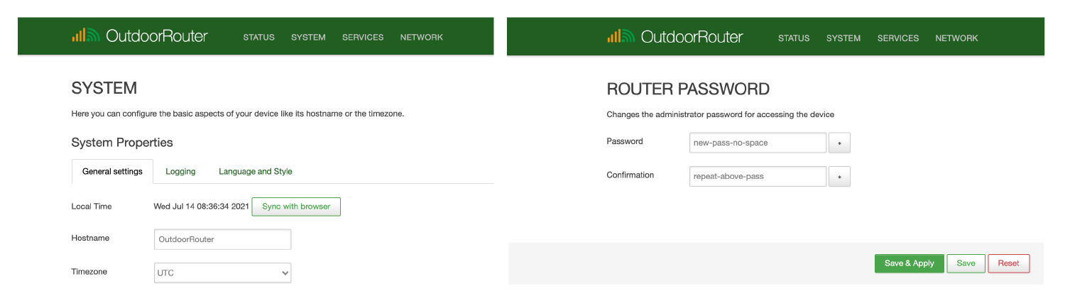
After accessing the router admin panel, navigate to ***"System > System"*** from the top menu. We will go to the below System Properties page.
## System Properties
### Time Zone
Under the General Settings tab, click the **"Sync with browser"** button to sync the time. \
The router will automatically sync with the time server after being connected to the internet.
Choose the correct time zone, then click the **"Save & Apply"** button on the bottom right corner to save your new settings.
### Host Name
You can customize the **"Hostname."** It displays in the top-left corner.
EZR34T-5G - System Properties and Router Password
## Administration
Go to ***System > Administration*** and input the new custom router password twice in the "Router Password" section, then click the ***Save & Apply*** button on the bottom right corner.
{% hint style="info" %}
Keep the new router's admin password in a safe place. If the password is forgotten, we can only reset the router firmware.
{% endhint %}
{% embed url="" %}
EZR34T - How to Set Router Password & WiFi Hotspots
{% endembed %}
# 4.3 WiFi Hotspots
## Wireless Overview
After accessing the router admin panel, go to ***Network > Wireless*** to check the Wi-Fi status.
* **Ra0 - MT7615E 802.11bgn** is the 2.4GHz WiFi module\
SSID: Outdoor-WiFi-xxxx-V4 is the 2.4GHz hotspot
* **Rax0 - MT7615E 802.11anac** is the 5.8GHz WiFi module\
SSID: Outdoor-WiFi-xxxx-V5 is the 5.8GHz hotspot
* **SSID | Mode: Client** -- is the Wi-Fi relay connection. \
It's not visible until set up the Wi-Fi relay.
* **Associated Stations** are the active Wi-Fi networks and their working status.
You can turn off both client and master SSID by clicking the "**Disable**" button. And re-active it by clicking the "**Enable**" button.
EZR34T-5G - WiFi Hotspots Wireless Overview Page
***
## Edit Wi-Fi Hotspot
On the above wireless overview page of "System > Wireless." Click the **"Edit"** button on the row of related SSID to enter their configuration page.
### i. Basic Wi-Fi Settings
In the tab of **General Setup**, you can monitor the network status and configure Wi-Fi operating Mode, Channel, Bandwidth, and Transmit Power.
Suggest using default settings unless there is a conflict.
{% hint style="info" %}
After connecting to a WiFi relay, the WiFi master SSID's Mode, Channel, and Width will be locked to the same settings as the connected Wi-Fi relay network.
If other 2.4GHz Wi-Fi hotspots are nearby, do not use 40MHz on "Width," and do not turn on "Force 40MHz mode" on the advanced settings.
{% endhint %}
### ii. Wi-Fi Country Code
In **Device Configuration**, click the **Advanced Settings** tab, check the Country Code field, and select the corresponding country code.
It is essential to ensure the Wi-Fi hotspot on your router meets the legal regulations in your country. The other configured Wi-Fi networks will use the same device settings.
EZR34T-5G - Advanced Wireless Network Settings
### iii. Wi-Fi SSID & Password
In the section of **Interface Configuration**, click the **General Setup** tab. You can edit the Wi-Fi hotspot's name on the **ESSID** field.
Click the **Wireless Security** tab to enter the encryption section and configure the Wi-Fi password.
* **Encryption:** Select an encryption method. The last option, *"WPA-PSK/WPA2-PSK Mixed Mode,"* is recommended for home and small office networks.
* **Cipher:** The *"Auto"* option is recommended.
* The **Key** is the Wi-Fi password. Input your password without space. Special characters are supported. The minimum length is eight characters. \
\* Do not leave it empty after choosing the encryption type.
* Other default settings are qualified for general usage.
Enable the checkbox of **Hide ESSID** to stop broadcasting the Wi-Fi hotspot but maintain the Wi-Fi connection. You should manually input the WiFI SSID and password to connect a new device when ESSID is hidden.
5G WiFi Hotspot SSID and Encryption
{% embed url="" %}
EZR34T - How to Set Router & Wi Fi Password
{% endembed %}
***
## Wi-Fi Relay
You can connect the outdoor router to another WiFi hotspot to get a backup Internet connection or extend the current WiFi network.
Go to ***Network > Wireless*** and open the wireless overview page.
1. Click the **"Scan"** button on the first row of ***"Ra0"** or **"Rax0"***. It will open a new page and scan the nearby WiFi hotspots. \
*Note: Ra0 is for connecting to 2.4GHz, and Rax0 is for connecting to 5.8GHz.*
2. Choose the WiFi hotspot you want to connect to from the page and click the **"Join Network"** button.
3. Enter the WiFi password on the "WPA passphrase" field. Leave the new network as **"wwan"** in the **"WAN/Mobile"** firewall zone.\
*!! Do not enable the "Replace wireless configuration" check box unless you intend to disable its own WiFi master hotspot.*
4. Click the **"Submit"** button on the bottom right corner to enter the Wi-Fi client configure page. Generally speaking, you can use leave all of them with no change.
5. Click the **"Save & Apply"** button to return to the wireless overview page. Wait 2\~3 minutes until the WiFi hotspot reboot.
5G CPE WiFi Relay Connection
{% hint style="info" %}
Ensure the WiFi source has a different IP range than the outdoor router.
We can repeat the above operations and connect to multiple WiFi hotspots. Please use a different "Name of the new network" and set the firewall to "WAN."
If failed to set up a WiFi relay connection, go to "Network > Wireless," delete the "SSID | Mode: Client," and repeat the above operation.
{% endhint %}
***
## WiFi Coverage
For better outdoor WiFi coverage, suggest installing the router in an open space with the fewest barriers nearby. To cover indoor spaces, you can install the router near the windows or doors.
You can also use an indoor router and link to the LAN port on the PoE injector.
# 4.4 5G-NR Modem
The default cellular modem settings can adapt to most operators and support carrier aggregation and LTE fallback.
## Device Status
After logging into the router, you can find the mobile modem device information below on the front page's right side. We can easily monitor the mobile modem working status in this section.
* **Mobile Modem** is the model of 5G-NR modem.
* **SIM Card** is the current SIM slot the router is using. You can change to use another SIM card under the Mobile interface settings.
* **SIM Status** is the working status of the inserted SIM card.\
If it shows "Connected," you can ignore the further modem settings on the below steps. Check the signals, APN, and protocol settings if it displays an error.
* **Phone Number** is the mobile phone number of the active SIM card. Some of the data plan SIM cards do not show the phone number.
* **IMEI Number**, short of International Mobile Equipment Identity number. It's a unique serial number of the mobile modem.
* **Mobile Operator** is the provider of wireless communications services. \
*\* Usually the same as the SIM card provider.*
* **Access Tech** is the current mobile network the router connects to, including LTE and 5GNR.
* **Mobile Signal Quality**\
`RSRP`: The average power received from a single reference signal.\
`RSRQ`: Indicates the quality of the received signal.\
`SNR`: The signal-to-noise ratio of the given signal.
***
5G-NR CPE Router Modem Device Status & Mobile Interface
***
## Mobile Interface
Go to ***Network > Interface*** to visit the interface overview page. Locate the ***Mobile** interface* on the second row. It shows the below information.
* **Protocol** is the current mobile protocol.
* **Uptime** is the total working time of the currently active mobile internet connection.
* **RX** is the download traffic, and **TX** is the upload traffic.
* **SIM** shows the current activated SIM card slot.
* **IPv4** is the mobile internet IP address, usually a private IP address.
{% hint style="info" %}
You can manually click the "Stop" or "Restart" button on the Mobile interface to kill the mobile connection or redial for a new link.
Do not click the "Delete" button on the Mobile interface. It will "**erase**" the mobile modem until reset the router.
{% endhint %}
###
### SIM Card & APN
**APN**, short for Access Point Name, is the gateway to access the mobile network. In general conditions, the router can use the default APN parameters prebuilt in the mobile modem to set up a connection.
Some mobile carriers use different APN parameters for the various data plans. After confirming the accurate APN address with the mobile operator, you can configure the APN settings on the mobile interface, as shown below.
1. After Accessing the router admin, go to ***Network > Interfaces***, and click the ***Edit*** button on the row of the **Mobile** interface.
2. On the tab of **General Setup**. You can choose the SIM card and enable the auto switch SIM card function when the router has two workable SIM cards.\
\
**Protocol:** Suggest using the default protocol **Mobile Data** unless the provider does not support it, which usually happens in rural areas.\
**Modem Device:** Do not change it unless switching the above "Protocol".\
**Active SIM Card:** Choose the SIM card you want to use.\
**Auto Switch SIM Card:** Enable this option to automatically switch to another SIM card when the above "Active SIM card" is offline.
3. Click the tab of related SIM cards to configure their APN and PIN settings.\
\
**APN:** Input the mobile carrier's APN gateway address.\
**PIN:** 4-digit code. If you have not changed it before, leave it empty.\
**Username:** Username of the APN gateway.\
**Password:** Password of the APN gateway.\
**Authentication:** Leave it as *"--Please choose--"* or choose *PAP* in most cases.\
**IP Connection:** Leave it as *"--Please choose--"* or choose *IPv4* in most cases.\
**Forbid Roaming:** Leave it unselected unless you need to disable the roaming function.
5G Router Mobile Interface Settings - APN Gateway
*For more details on the APN settings, check the tutorial at* [*https://www.outdoorrouter.com/apn/*](https://www.outdoorrouter.com/apn/)*.*
Click the **Save & Apply** button on the bottom right corner to apply the new settings. It will jump back to the interface overview page.
Wait 1-2 minutes until the mobile modem reconnects to the mobile network.
### Mobile Protocol
Some carriers or data plans might not support the default **Mobile-Data protocol**. For example, in UK rural areas, the EE and Vodafone can only use the PPP protocol.
*Please check the protocol tutorial at* [*https://www.outdoorrouter.com/protocol/*](https://www.outdoorrouter.com/protocol)*.*
# 4.5 LAN and WAN
The EZR34T-5G is a standalone router with LAN WAN interfaces and a DHCP server. After logging into the router, go to Network > Interfaces to view and manage the LAN and WAN interfaces.
***
5G CPE Router Interface Overview LAN WAN and Mobile
{% hint style="info" %}
Rx/Tx indicates the real-time data stream instead of the speed.
The color on the interface is not corresponding to its connection status.
{% endhint %}
***
## Intranet LAN
**LAN**, or local area network, enables the 5G mobile internet to all the devices connected to the 5G CPE router. To edit the router IP address and DHCP server settings, go to **Network > Interface**, and click the **Edit** button on the first row of the LAN interface.
5G CPE Router Local LAN Network Settings
### Router IP
When there is more than one router in the same network and working on the same IP range of 192.168.30.x, please change their router IP to a different one to avoid IP conflicts.
After clicking the Edit button on the LAN interface, go to the tab of General Setup.
* **Protocol:** Always use the "Static address" protocol for the LAN interface.
* **IPv4 Address:** It's the EZR34T router's IP address. Ensure it ably to the private IP formats when changing it.
* IPv4 Netmask: It defines how "large" the LAN network is.
* IPv4 Broadcast: The DHCP clients use the broadcast to find and send requests to their respective servers.
{% hint style="info" %}
**Private IP address ranges**
Class A: 10.0. 0.0 — 10.255. 255.255
Class B: 172.16. 0.0 — 172.31. 255.255
Class C: 192.168. 0.0 — 192.168. 255.255
{% endhint %}
###
### Physical Ports
There are two physical RJ45 ports on the router. eth0.1 is bound to the LAN interface, and eth0.2 is bound to the WAN interface. Both eth0.1 and eth0.2 supports PoE power input.
The LAN interface should be bound to eth0.1 with no change when you use a PoE injector to output Ethernet signals. You can also bind eth0.2 to the LAN interface when you need two of the LAN ports.
### Firewall Zone
Do not change the firewall settings unless you have configured the alternative firewall zone correctly.
***
## DHCP Server
The DHCP server can automatically configure connected devices' TCP/IP settings and lease out an IP address from the available IP pool.
On the LAN interface configuration page, scroll down and find the section of the DHCP server. Modify the DHCP server settings under the tab of General Setup.
5G Router LAN DHCP Server
**Ignore Interface:** Enable this checkbox will turn off the router's DHCP server. The connected devices will no longer be able to obtain local IP from the router and can not access the mobile internet.
**Advanced Settings > Force:** Enable this option when there is more than one DHCP server in the entire network.
Field
Default
Description
Field
Default
Description
Start
100
The start of DHCP IP pool.
For example, if the router’s LAN IP is 192.168.30.1 and netmask is 255.255.255.0, a valid IP address should be in the range of [192.168.30.0…192.168.30.254]
* 192.168.30.255 is a special unavailable address.
Limit
150
Define the IP addresses the DHCP server can lease out.
Continuing from the above example: if the start address is 192.168.30.100 and the server can lease out 150, available addresses will be from 192.168.30.100 to 192.168.30.249.
Lease time
12 hours
The duration of an IP lease. Leased-out addresses will expire after the specified period, and a new DHCP lease must be requested.
If the device stays connected, its lease will be renewed after half of the specified amount of time passes.
For example, if the lease time is 12 hours, then every 6 hours, the device will send a request to the DHCP server asking to renew its lease.
The lease time can be set in hours (h) or minutes (m). The minimum time that can be specified is 2min (2m). Use Infinite to assign lease time forever.
### Static IP Address
If the DHCP server was disabled on the router, we could access the router with a static IP address. Below is an example of static IP address settings. Ensure the gateway IP address and subnet mask address match the router configurations.
Computer IP: 192.168.30.100 (Inside the default DHCP range of 100\~249)\
Subnet Mask: 255.255.255.0 (also called 24 on Windows)\
Gateway (Router IP): 192.168.30.1
#### How to configure a static IP address?
On iPhone: Goes to "Settings > Wi-Fi > Advanced."\
On Android phone: Goes to "Settings > WLAN > Advanced"\
On Mac: Goes to "System Preferences > Network > Wi-Fi > Advanced > TCP/IP"
**On Windows 10**\
Goes to "Start > Control Panel > Network & Internet > Change Adapter Settings.\
Change the "Local Area Connection > Properties (on the right click) > TCP/IPv4 > Properties > General".\
Enter the above static IP address, subnet mask, and gateway. Click "Ok" to exit settings.
***
## WAN Network
WAN stands for Wide Area Network. The EZR34T router's WAN network consists of the physical WAN port, WiFi relay link, and mobile modem.
The physical WAN port is bound to RJ45 port eth0.2. When the PoE injector is linked to the WAN port, you can input a landline internet to the router.
The WAN interface (eth0.2) has enabled the DHCP client protocol, and it will automatically obtain the IP address and internet traffic from the source router.
# 4.6 Recovery
## Reboot
Like a regular computer, the mobile router is a Linux-based operating system. Rebooting the router can solve mysterious problems, fix Internet connectivity issues, and improve security.
The Internet provider assigns a temporary IP address which can be changed when timeout. If the router misses the change, the Internet connection might become slow. The same can happen if too many devices are connected to the router. The routers found channels with less traffic during a reboot and raised the performance speeds.
### Soft Reboot
After accessing the router, go to "System > Reboot" for a **soft reboot**.
### Hard Reboot
To run a **hard reboot**, please unplug the PoE injector wait a couple of seconds, and then connect it again.
{% hint style="danger" %}
Do not disconnect from the PoE injector while flashing firmware and resetting the router.
{% endhint %}
***
## Backup & Restore
The router provides an easy way to back up and restore the previous configurations. Please back up your router configurations before making changes to the router.
**Backup Configurations**
After accessing the router, navigate to "System > Backup / Flash Firmware > Action: Backup." \
Click the "Generate Archive" button to download the archive of current router configurations.
Turn off the auto unzip function on Sarafi or use other web browsers to download the backup archive file. Do not modify the archive file to avoid failure of MD5 verification while restoring it.
**Restore Configurations**
To restore previously saved router configurations from the local PC, please navigate to "System > Backup / Flash Firmware > Action: Restore." \
Click the "Choose File" button to load the previously downloaded archive file. \
Click the "Upload Archive" button to upload the archive.
***
## Factory Reset
A factory reset will erase configurations and return the router to its setting just after flashing.
{% hint style="danger" %}
Do not turn off power while resetting the firmware.
Before disconnecting from the power source, ensure the router completes the resetting progress and successfully reboots.
{% endhint %}
### Soft Factory Reset
If you want a clean slate, it's no need to flash the firmware again.
1. After accessing the router, go to "System > Backup / Flash Firmware > Action: Restore."
2. Click the "Perform Reset" red button and "Confirm" on the pop-up window.
3. The router will go to the System - Erasing page. The system indicator flashes while resetting.
4. Wait 3-5 minutes until the router completes the resetting progress and reboot.
### Hard Reset
Open the enclosure and find the physical round **Reset** button nearby the DC socket.
1. When the router is powered on, wait a few minutes until the router successfully boots up and the System indicator stops flashing.
2. Press and keep pushing the Reset button for at least **5 seconds**. The system indicator will start to flash rapidly.
3. Release the **Reset** button.
4. The router starts resetting the firmware, and the system indicator flashes.
5. Wait 3-5 minutes until the router completes the resetting progress and reboot.
# Advanced Settings
# Traversal Cloud
Traversal Cloud is our secure NAT tunnel tool to provide remote control function on the 4G/5G routers and connected hosts. For more information about the cloud features, please visit .
After enabling the **Traversal Cloud**, you can access and control the router anytime, anywhere, on a web browser. It offers the easiest way to look over your networks. No public IP address and DDNS configuration are required.
Traversal Cloud - Remote 4G/5G Control
## **Enable**
The traversal cloud is turned off by default. You can follow the below steps to enable it.
1. Log in to the router, go to "Services > Traversal Cloud."
2. Click the " Enable " checkbox and "Save & Apply."
3. Click the cloud address or copy it to the address bar on a web browser to access the router.
{% hint style="info" %}
Recommended to set up a strong router password before enabling the traversal cloud.
No guarantee of this free service. Some cellular carriers might block the port number used by this cloud connection.
{% endhint %}
##
## Debug
If unable to access the cloud address, please check the below factors.
1. Ensure the traversal cloud has been **enabled**. After enabling the checkbox, please click the "Save & Apply" button.
2. Before accessing the traversal cloud server, the router must have an Internet connection. Check the Internet connection on the router.
3. If you once turned off the traversal cloud function within a power cycle, please reboot the router to refresh the traversal connection session.
# Firewall Settings
The router firewall controls the forward packet streams from incoming network interfaces to outgoing network interfaces.
Firewall rules add another layer of granularity to what can be forwarded across interfaces and which packets can be inputted and outputted.
***
## Firewall Zones
The firewall can collect interfaces into zones to filter traffic logically. A zone can be configured to any set of interfaces. This simplifies the firewall rule logic somewhat by conceptually grouping the interfaces:
* A rule for a packet originating in a zone must enter the router on one of the zone's interfaces,
* A rule for a packet being forwarded to a zone must exit the router on one of the zone's interfaces.
After accessing the router, go to "Network > Firewall" to enter the "Firewall - Zone Settings." The "SYN-Flood Protection" is enabled by default. You can use the default firewall zone settings in most conditions.
***
## Port Forwarding
Port forwarding applies *network address translation* (NAT) and redirects a communication request from one address and port number combination. Port Forwarding allows remote computers to connect the outdoor router within a private local-area network (LAN).
### General Settings
Log in to the router, go to "Network > Firewall."
* Under the tab of "General Settings," change forward to "Accept."
* In the **Zones** section, change the **Forward** on the row of **WAN** from "Reject" to "Accept."
* Click the **Save & Apply** button on the bottom right corner.
### Public Port Forwards
Click the tab "Port Forwards" to enter the configure section on the **New port forward** section:
1. **Name:** Enter the reference name. e.g., *Test*
2. **Protocol:** Select from "TCP, UDP, and TCP+UDP"
*If you don't know the protocol, please choose TCP+UDP. Select TCP or UDP if you know whether it is TCP or UDP. It can effectively reduce resource consumption.*
3. **External Zone:** Select "WAN"
4. **External Port:** Set the port number you want to access from the external network\
*Suggest selecting the WAN port between 1025\~25534. Do not use the standard ports occupied by the other services such as 23, 80, 433, 3389, 7700, 10080, etc.*
5. **Internal Zone:** Select "LAN"
6. **Internal IP Address:** Select from the list of connected intranet hosts.\
*If you can not find the host in the list, please re-check the* [*Local network settings*](broken://pages/-LwGn9Etiuxwlh0jKSdB#1-lan-bar-lan)*.*
7. **Internal Port:** Enter the port number which needs to forward from the intranet host
8. Click the button "Save & Apply" to execute the new settings.
**NAT Loopback** is turned on after saving a new port forward rule. It allows the intranet terminal to access the local hosts using the public IP address of the routed external network interface. To reduce the consumption of router resources, you can click the **"Edit"** button on the saved port forward rule list to disable it.
{% hint style="info" %}
The public port forwarding relies on a public IP address. Most of the 4G internet connection obtains a private IP address. Please get the public IP from the 4G carrier to activate the public port forwarding.
Make sure to use a WAN port the 4G carrier has not blocked.
Except for a public 4G IP address, you can also try to forward it to OpenVPN or WireGuard server through the VPN tunnel.
{% endhint %}
***
## Open New Port
After accessing the router, go to "Network > Firewall > Traffic Rules: Open port on router" to add a new port on the 4G router.
* **Name:** Input name of the new port
* **Protocol:** Choose from TCP or UDP
* **External port:** The new port number
After entering the above parameters, click the "Add" button. Then click the "Save & Apply" button on the bottom right corner. You will find the new port on the "Traffic Rules" list.
# SSH Terminal
The command-line interface (CLI) means interacting with the router system where the user issues command to the router system in the form of command lines.
Secure Shell (SSH) is a cryptographic network protocol to access the router’s command-line interface. The router supports various ways to access the command-line interface.
## **Web Terminal**
After accessing the router, go to "System > Terminal."
Input the default username ***root*** and ***the router password***. You will then receive the welcome message on the web terminal interface.
```
OutdoorRouter login: root
Password:
BusyBox v1.28.4 () built-in shell (ash)
╔═╗╦ ╦╔╦╗╔╦╗╔═╗╔═╗╦═╗╦═╗╔═╗╦ ╦╔╦╗╔═╗╦═╗
║ ║║ ║ ║ ║║║ ║║ ║╠╦╝╠╦╝║ ║║ ║ ║ ║╣ ╠╦╝
╚═╝╚═╝ ╩ ═╩╝╚═╝╚═╝╩╚═╩╚═╚═╝╚═╝ ╩ ╚═╝╩╚═
---------------------------------------
☼ ☼ ☼ OUTDOOR ROUTER ❅ ❅ ❅
---------------------------------------
root@OutdoorRouter:~#
```
{% hint style="info" %}
For security reasons, the router password does not appear while inputting it. Just input it and press "Enter" on the keyboard to enter the web terminal.
*The web terminal is unavailable under the Traversal Cloud mode.*
{% endhint %}
## SSH Software
### **Linux & Mac**
For Linux and Mac computers, the most common tool in the system Terminal.
* Open a new Terminal window and type `ssh root@192.168.30.1` and press *Enter*.
* If this is your first time logging in, you might be asked to clarify whether you want to log in. In that case, type yes and press "Enter" on the keyboard.
* Then type in the router’s admin password and press "Enter" to log in to the terminal.
{% hint style="info" %}
If the router has changed configurations, you might need to clear the stored SSH key information with this command ***ssh-keygen -R 192.168.30.1***.
{% endhint %}
### **Windows**
For Windows computers, the most common SSH tool is **PuTTY**.
* Launch PuTTY and select the SSH option under the "Connection Type" field.
* Type the router IP **192.168.30.1** into the **Hostname** field.
* Type SSH port **22** into the **Port** field.
* Click the "Open" button.
* In the next window, type in the login name **root** and press "Enter."
* Type in the router’s admin password and press "Enter" again.
* You should be greeted with a message.
# Diagnostics
We can use the pre-built tools and web terminal to test the internet connection. After login router admin panel, go to "Network > Diagnostics."
## Ping Tool
Use the "Ping" tool to ping a public DNS server or website to test latency. If returning a "Bad address" error, the internet connection is not working. If ping results have high latency, such as more significant than 300ms, the Internet speed is not fast.
## System Log
The router's system log includes the records of events and activities on the router, such as various system events, operations, errors, and warnings related to the router's firmware and software.
We can go to "Status > System Log" and check the related error records when some connectivity error happens.
## Debugging
If you need our help debugging the problems, please send the screenshot of the router's home page, paste the above-mentioned system log, and send them to us by email.
# EZR34T-LTE Router
EZR34T-LTE has an outdoor waterproof enclosure and a built-in 4G LTE mobile modem with dual SIM card slots.
The 4G LTE modem inside the outdoor router uses a Nano SIM card to connect to mobile networks and provide broadband mobile internet connections on the Wi-Fi hotspots and Ethernet port.
The outdoor enclosure was die-casted from ADC12 aluminum under 100-ton pressure and coated with a white weather-proof coating. O-rings, seals, and gaskets protect the 4G router against water and dust. The durable enclosure provides waterproof protection in demanding environments and works in a temperature range of -40° \~ +80° Celsius.
The image below shows the basic working principle of the outdoor 4G router.
The outdoor 4G router has a standalone MIMO Wi-Fi hotspot with a DHCP server and supports a wireless Wi-Fi relay connection. It has a powerful Wi-Fi booster inside with transmission speeds of up to 1,200Mbps. The Wi-Fi signal can cover 150-300 yards in the open space.
Complying with the 802.3af/at PoE standard, the outdoor 4G router uses a LAN cable to transmit both DC power and Ethernet data. It supports a maximum 50-meter LAN cable. You can also power it up with a 12V DC power adapter. To extend the 4 G internet to an indoor area, connect a network switch, second router, or computer to the LAN port on the PoE injector.
# Hardware
Outdoor 4G router is an industrial-grade 4G LTE cellular modem with standalone WiFi hotspots for use in the outdoor environment and rugged deployments.
{% content-ref url="/pages/bSz2SuDi3D3gP91I39yE" %}
[1.1 Package Contents](/lte/hardware/package)
{% endcontent-ref %}
{% content-ref url="/pages/s23IgzGu5xWZWXHybCFU" %}
[1.2 Interfaces Overview](/lte/hardware/interface)
{% endcontent-ref %}
***
## Hardware Specifications
### **EZEN4X Motherboard**
CPU:
MTK7621 MIPS1004Kec
Frequency:
880MHz
Memory:
DDR3 RAM 256MB
Flash:
SPI FLASH 16MB
SIM card slot:
Nano-SIM Cards (12.3×8.8mm)
WAN/LAN port:
10/100/1000Mbps on PoE adapter
Indicator:
SIM Card / Power / System / WiFi / Mobile
Temperature:
Working: -30 to +70°C Storage: -40 to +85°C
Humidity:
0%~100% RH
Physical Interface:
1 x PoE & LAN and 1 x PoE & WAN
2 x Nano SIM card slots 1 x Reset button
### **Omni Antenna**
2 x 4G LTE Antenna:
Frequency: 700~960 / 1710~2700MHz
Gain: 3~4dBi / V.S.W.R.: ≤ 2.0
2 x Wi-Fi antenna:
Frequency: 2400~2500 / 5150~5850MHz
Gain: 4~5dBi / V.S.W.R.: ≤ 2.0
Measurement:
Φ22×180mm
Connector:
N Male
Polarization:
Vertical
Impedance:
50 Ω
Max Input power:
10 Watt
### **Wi-Fi Hotspot**
Wi-Fi standards:
IEEE 802.11 a/b/p/g/n/ac IEEE 802.3 and IEEE 802.3u
MIMO Wi-Fi:
2T2R Wave 2.0 MU-MIMO
Transmission rate:
1200Mbps
Frequency:
2.4GHz - 2412~2484 MHz
5.8GHz - 5180~5825 MHz
Channel:
2.4GHz - 1~13
5.8GHz - 149, 153, 157, 161, 165
Bandwidth:
20/40 MHz or Auto
Output power:
802.11b: 27±2dBm
802.11g: 25±2dBm
802.11n: 23±2dBm
802.11ac: 26±2dBm
Concurrent user:
120 users
### **PoE Injector**
Input:
110~240VAC 50/60Hz
Output:
52Volt 0.5Amps
LAN Cable:
30-feet LAN cable included. Max 320-feet.
PoE Wiring:
DC+ 4,5 | DC- 7,8 Ethernet on all wires
DC Socket:
Takes wide-range 9~52V DC power
DC Jack - Ø5.5/2.1mm / Length 10mm
### **Firmware**
Login:
IP address: 192.168.30.1
Password: none
Platform:
Windows / Mac / Linux / etc
# 1.1 Package Contents
The package includes the below contents along with free 4G router firmware.
After receiving the package, please check if all components below are included.\
Firstly, open the box from the **openside**.
Contents in the first layer of the black sponge\
1 x EZR34T outdoor router\
2 x 4G LTE antennas\
2 x Wi-Fi antennas
Remove the router and antenna and pull out the black sponge from the central rhombic hole.\
The items below are in the black clamshell's second layer.
1 x L-shape bracket\
1 x PoE Injector\
1 x 10-meter LAN cable\
2 x U-boots with holders\
1 x T-shape wrench
{% hint style="info" %}
Please keep the original package for a few weeks. You can also store the other devices in the rugged 5-layer corrugated box.
{% endhint %}
# 1.2 Interfaces Overview
Introduction to the enclosure and outside physical interfaces of the outdoor router.
## Interfaces
Introduction to the outside physical interfaces of the outdoor 4G router.
EZR34T-LTE router has 4x antenna sockets, 1x gland socket, 1x breather valve, and 1x lock hole.
All of the antenna sockets are N-female type. 4G antenna sockets are on the top side, and Wi-Fi antenna sockets are on the bottom.
***\[1\~6]** are the embossed numbers on the enclosure. \[2] The top side is for spare uses.*
There are two types of ends on the T-shape wrench. The hexagon end fits the hexagon bolts on the lid. The cross end is fit to cross-headed screws on the backside. Use one of the Hexagon ends on the wrench and turn in an anti-clockwise direction to lose the bolts on the lid. Then, we can open the enclosure.
***
## Seal the Enclosure
Close the lid & press it with your hand. Then, use the hexagon end on the T-wrench to tighten four pieces of bolts on the lid. After closing the enclosure, please review and ensure no gap after tightening the screws!
# 1.3 Install Antennas
The outdoor router use MIMO antennas on both mobile and Wi-Fi connections.
There are four antenna sockets on the outdoor router. Firstly, find the embossed numbers #1\~6 on the enclosure.
**#1 & 3** on the top side are for 4G antennas. #1 is the 4G main input port.\
**#4 & 6** on the bottom side are for the Wi-Fi antennas.
The antennas have 4G or WiFi text engraved on one side of the hexagon connector.
Put 4G and WiFi antennas on the corresponding sockets and turn the hexagon part clockwise to tighten the antenna on the router. Make sure the antennas are installed tightly.
{% hint style="info" %}
While installing the antenna, put the router device in a vertical or horizontal direction to avoid bending the pins in the antenna connector.
The default Omni antennas are polarized vertically. Please always use the antenna in a vertical direction.
Adjust the flat side to point towards the cell tower's direction for better performance.
{% endhint %}
***
## Upgraded Antenna
All of the base antenna connectors are N-female type.
If the 4G RSRP signal strength is below -105dBm, suggest upgrading the 4G antennas to a directional LPDA antenna or MIMO panel 4G antenna and improving the signal reception.
If using the router on an RV or boat, suggest upgrading to FRP or MIMO Omni antennas.
# SIM Card & PoE
Insert a SIM card and connect to the PoE power to boot up the outdoor 4G router.
# 2.1 Insert SIM Card
The outdoor 4G router requires inserting at least one SIM card to connect to the mobile networks. The SIM card is not included with the router.
Use a Nano SIM card (12.3x8.8mm) on the 4G router. If it's a new SIM card, please follow the instructions from the mobile carrier to activate it.
{% hint style="info" %}
### Clean the SIM Card
If the 4G router cannot detect the SIM card or gets the error message "SIM card unavailable," first verify if the SIM card is inserted correctly. Secondly, please check if the SIM card is clean, especially on the golden contacts. If there is dust, dirt, or oil on the SIM card, you can follow the tips to clean it.
{% endhint %}
{% hint style="warning" %}
Please always **turn off the power** while inserting or removing the SIM card.
{% endhint %}
###
### Step by Step
1. Open the enclosure and locate the SIM1 slot in the top right corner of the router motherboard.
2. Hold the lid of the SIM card slot and slide left to open the lid.
3. Put a Nano SIM card in the SIM card slot. There is only one correct way to settle the SIM card—the gold pins should be face down, and the notch should be in the top right corner.
4. Cover the SIM lid and slide it right to lock it.
{% hint style="info" %}
i. Please use an unlocked and activated SIM card.
ii. Please insert a SIM card in the SIM#1 slot on the SIM card holder unless you choose to use secondary SIM#2 on the mobile interface.
iii. The 4G router can work well with a single SIM card. You can also insert an extra SIM card as a backup connection. To activate the backup connection, please enable the auto-switch option on the mobile interface.
{% endhint %}
# 2.2 PoE and Power
The outdoor router takes electric power from the PoE injector. It can also receive WAN or provide a LAN Ethernet connection through the PoE injector.
Complying with the 802.3af/at PoE standard, the outdoor 4G router uses a LAN cable to transmit both DC power and Ethernet data. The package includes a 52-volt standard PoE injector and a 10-meter outdoor-grade LAN cable.
The PoE injector supports a maximum 50-meter-long LAN cable. Use CAT5e or higher-grade LAN cable and ensure it's the TIA/EIA568B wiring. Please refer to the image below.
***
## **Connect to PoE Injector**
Please refer to the image and follow the below steps to connect the router to the PoE injector.
### Step-by-step
1. **Take apart the PoE gland.**\
Turn the white color cap off from the gland in an anti-clockwise direction.\
Then, push out the orange color stopper from the inside direction of the barrel connector.
2. **Take one end of the LAN cable through the cap.**
3. **Put the LAN cable through the barrel screw** and plug in the **PoE & LAN** port on the motherboard.
4. **Clamp the stopper on the LAN cable** and settle it in the barrel.\
\* The smaller end of the orange color stopper should face the outside.
5. **Turn the cap clockwise** to tighten it on the barrel screw.
6. Connect another end of the LAN cable **to the PoE port on the PoE injector**.
7. Connect the AC plug on the PoE injector to an electrical outlet after finishing all the hardware installation.
### PoE Ethernet Connection
The PoE injector has two RJ45 ports. The PoE port outputs 52V 0.5Amps DC power to boot up the 4G router.
After the 4G router is connected to the mobile network, we can connect a computer, another router, or network switch to the LAN port on the PoE injector and get an Ethernet connection.
Make sure the computer or another router turns on DHCP client mode. Then, they could automatically obtain a local IP address and connect to the internet.
#### Remarks:
**Exchange AC Plug on PoE Injector**\
To exchange the AC plug on the PoE injector, press and hold the Push button, then push the AC plug upward to remove it. Then, install another AC plug on it.
**Exchange LAN Cable**\
The package includes a 10-meter outdoor-grade LAN cable. You can use a maximum 50-meter LAN cable. Use Cat5e or higher-grade LAN cable and ensure it's the TIA/EIA568B wiring. An outdoor-grade LAN cable is recommended for use in the outdoor environment. The Ethernet signal will be attenuated when the LAN cable is longer than 50 meters. You can use a PoE extender to reduce the attenuation on a longer LAN cable.
***
## Alternative Power
### PoE Switch
You can use an IEEE802.3af/at standard PoE switch to power up the 4G router. Connect the 4G router to one of the PoE ports on the PoE switch.
### 12Volt Power
We can boot up the outdoor router with a range of 9\~52 Volt DC power. Use the DC plug to connect to the DC socket on the motherboard. The PoE gland can take an extra DC power cable. The suggested DC power current is 12 Volt 1.5 Amps.
If both DC power and PoE power are connected, the outdoor router will use the first connected power source. The router seamlessly switches to another power source if one cuts off power.
{% hint style="danger" %}
Do not use an overloaded electrical current on the DC socket!\
The suggested typical DC power is 12Volt 1\~2Amps.
{% endhint %}
# 2.3 Indicators
The EZR34T-LTE outdoor router has seven indicators. The SIM card indicator is in the top left corner.
From top to bottom on the 4x indicator sets, the left sides are system & Wi-Fi, and the right is mobile and power. Below are the indicator descriptions.
Indicator
Status
Description
System
Green
This light indicates that the router is receiving power. If it's lit solid green, then the router has booted successfully.
Flash
The router system is booting up. The system indicator flashes while resetting or flashing the firmware.
Off
No light at all indicates that the router is not receiving power. Check the PoE socket connected to the motherboard and check the PoE adapter. You might need to test an alternate power socket if the router doesn't power on.
Wi-Fi
Green
This light indicates that the modem is sending a Wi-Fi signal. You can see and connect to the Wi-Fi network if the light is green.
Flash
If you are connected to the Wi-Fi hotspot, it will flash green to indicate data going to and from the router. If the router is connected to another Wi-Fi hotspot (Wi-Fi relay), it will also flash because it has the data flow.
Off
If it's off, your router no longer sends a Wi-Fi signal. You can log in to the router admin and turn on the Wi-Fi master hotspot.
Mobile
Green
These lights indicate which SIM card the router is using. It uses the SIM1 by default.
Power
Green
Turn on after connecting to an eligible PoE injector or DC power source.
# Bracket & Mounting
The outdoor router has a patented waterproof enclosure and white weather-proof coating for work in demanding environments.
# 3.1 Signal Coverage
The router should be installed in a suitable location, such as elevated, near a window, and away from obstructions and RF equipment.
Cellular signal quality is crucial to mobile internet speed and stability. Ensure there is fair signal coverage where you will install the router.
## Choose Location
You can run a field test at the position where you want to install the outdoor router and check the signal strength. The easiest way is to use a smartphone and check the 4G LTE signal bars. The outdoor router could work well as long as you have "Good" LTE signal reception.
To measure the signal quality accurately, please check the tutorial at
#### LTE Signal Definition Chart
Quality
RSRP (dBm)
RSRQ (dB)
SNR (dB)
Excellent
> -80
> -10
> 20
Good
-80 to -90
-10 to -15
13 to 20
Poor
-90 to -100
-15 to -20
0 to 13
Bad
< -100
< -20
< 0
**Definition of LTE Signal Strength**
**Excellent:** Maximum speed and data throughput.\
**Good:** Stable connection and good data throughput.\
**Poor:** Maintain data connection with restricted throughput.\
**Bad:** Connection drop or unable to keep a stable connection.
# 3.2 Install On A Pole
Find a pole with a diameter of Ø35\~50mm and in a vertical or horizontal direction. The pole is not included in the package.
## L-Shape Bracket
Find the M6 standard cross-head screws or lose them from the backside of the enclosure.\
Use the cross end of the T-wrench to install the L-shape bracket on the backside of the enclosure.
There are multiple ways to fix the bracket on the enclosure. Make sure the longer side of the bracket is in the rectangular cross direction to the pole.
Pole Installation
## Install on A Pole
1. Clasp the pole with the U-bolts and holders.
2. Attach them on either side of the L-shape bracket.
3. On another side of the bracket, put washers, spring washers, and hex nuts on U-bolts.
4. Use an M10 spanner to turn the hex nut and tighten the bracket on the pole.
If you have doubts, please refer to the [case studies](https://www.outdoorrouter.com/case-studies/) to check where and how to install the router.
# Firmware Configuration
Powered by open-source firmware, the outdoor LTE router is plug-and-play, easy to use, root authority granted, and with advanced tools.
# 4.1 Connect & Login
Introduction of how to log in outdoor router's admin panel.
After connecting to PoE power, the outdoor router will take 2\~3 minutes to boot up. We can use a phone or computer to join its open Wi-Fi hotspot "**Outdoor-WiFi-xxx-V4/5**" or connect to the LAN port on the PoE injector.
After connecting with Wi-Fi or LAN, open a web browser, enter the router IP\
🔗 on the address bar.
The default setting has no password. Click the ***"Login"*** button to access the router's admin panel.
Login Admin Panel
{% hint style="warning" %}
If unable to access the router, please check the Wi-Fi or Ethernet connection. If you use a static IP address, ensure the phone or computer has turned on DHCP mode.
On some computers, we need to clean the web browser's cache.
The default URL prefix is **http\://** instead of https\://.
{% endhint %}
{% hint style="info" %}
The default Wi-Fi hotspot has no password.\
The default router admin has no password either.
{% endhint %}
# 4.2 System Admin
Basic system settings that should be changed on outdoor 4G router.
After accessing the router admin panel, navigate to ***"System > System"*** from the top menu. We will go to the System Properties page below.
## System Properties
### Time Zone
Under the General Settings tab, click the **"Sync with browser"** button to sync the time.\
The 4G router will automatically sync with the time server after being connected to the internet.
Choose the correct time zone, then click the **"Save & Apply"** button in the bottom right corner to save your new settings.
### Host Name
You can customize the **"Hostname."** It is displayed on the top left-side corner.
System Properties and Router Password
## Administration
Go to ***"System > Administration,"*** input the new custom router password twice in the section of *"Router Password,"* then click the **"Save & Apply"** button on the bottom right corner.
{% hint style="warning" %}
Keep the new router's admin password in a safe place. If the password was forgotten, you must reset the firmware system.
{% endhint %}
{% embed url="" %}
EZR34T - Set Rotuer Password & WiFi Hotsptos
{% endembed %}
# 4.3 Wi-Fi Hotspots
The default Wi-Fi hotspot "Outdoor-WiFi-xxx" and it is non-encrypted.
## Wireless Overview
After accessing the router admin panel, go to ***"Network > Wireless"*** to check the Wi-Fi status.
* **Ra0 - MT7615E 802.11bgn** is the 2.4GHz WiFi module\
SSID: Outdoor-WiFi-xxxx-V4 is the 2.4GHz hotspot
* **Rax0 - MT7615E 802.11anac** is the 5.8GHz WiFi module\
SSID: Outdoor-WiFi-xxxx-V5 is the 5.8GHz hotspot
* **SSID | Mode: Client** -- is the Wi-Fi relay connection.\
It's not visible until the Wi-Fi relay is set up.
* **Associated Stations** are the active Wi-Fi networks and their working status.
You can turn off both the client and master SSID by clicking the "Disable" button and reactivate them by clicking the "**Enable**" button.
WiFi Hotspots - Wireless Overview Page
***
## Edit Wi-Fi Hotspot
On the above wireless overview page of "System > Wireless." Click the **"Edit"** button on the row of related SSID to enter their configuration page.
### i. Basic Wi-Fi Settings
In the Device Configuration section, in the General Setup tab, you can monitor the network status and configure Wi-Fi operating Mode, Channel, Bandwidth, and Transmit Power.
Suggest using default settings unless there is a conflict.
{% hint style="info" %}
After connecting to a Wi-Fi relay, the Wi-Fi master SSID's Mode, Channel, and Width will be locked to the same settings as the connected Wi-Fi relay network.
{% endhint %}
{% hint style="warning" %}
If other 2.4GHz Wi-Fi hotspots are nearby, do not use 40MHz on "Width," and do not turn on "Force 40MHz mode" on the advanced settings.
{% endhint %}
### ii. Wi-Fi Country Code
In **Device Configuration**, click **Advanced Settings**, check the Country Code field, and select the corresponding country code.
It is essential to ensure the Wi-Fi hotspot on your router meets the legal regulations in your country. The other configured Wi-Fi networks will use the same device settings.
WiFi Hotspot Advanced Settings and WiFi Country Code
### iii. Wi-Fi SSID & Password
In the **Interface Configuration** section, click the **General Setup** tab. You can edit the Wi-Fi hotspot's name on the **ESSID** field.
Click the **Wireless Security** tab to enter the encryption section and configure the Wi-Fi password.
* **Encryption:** Select an encryption method. The last option, *"WPA-PSK/WPA2-PSK Mixed Mode,"* is recommended for home and small office networks.
* **Cipher:** The *"Auto"* option is recommended.
* The **Key** is the Wi-Fi password. Input your password without space. Special characters are supported. The minimum length is eight characters.\
\* Do not leave it empty after choosing the encryption type.
* Other default settings are qualified for general usage.
WiFi Hotspot SSID and Encyption Settings
**Remarks:**
Enable the checkbox **Hide ESSID**, and the router will stop broadcasting the Wi-Fi hotspot but maintain the Wi-Fi connection when manually entering the Wi-Fi hotspot name and password.
**WMM**, *Wi-Fi Multimedia*, is an automated way of handling Quality of Service (QoS) on the Wi-Fi network that provides improved video and voice performance over the wireless network.
{% embed url="" %}
EZR34T - How to Set WiFi Hotspot & Router Password
{% endembed %}
***
## Wi-Fi Coverage
For better outdoor WiFi coverage, suggest installing the router in an open space with the fewest barriers nearby. To cover indoor spaces, you can install the router near windows or doors.
You can also use an indoor router and link to the LAN port on the PoE injector.
***
## Wi-Fi Relay (Repeater)
You can connect the outdoor router to an existing WiFi network. The outdoor router will obtain internet connectivity through the linked hotspot and broadcast the signal to extend the coverage range.
Please check the step-by-step tutorial on setting up a Wi-Fi relay.\
***
## Guest Wi-Fi
A guest WiFi hotspot can provide visitors with internet access without compromising the main network's security. Enabling a guest WiFi hotspot to provide internet access to guests and add a security layer by keeping guest devices separate from the master network.
Please check the step-by-step tutorials on setting up Guest WiFi hotspots.\
# 4.4 Mobile Modem
Monitor status and configure APN and Protocol on the Mobile interface.
## Device Status
After accessing the router admin panel, you can find the **"Device"** section on the right side of the front page. It includes most of the SIM cards and mobile modem working statuses. Click the "**Reacquire**" button to update the mobile connection status.
* **Mobile Modem** is the 4G LTE modem model.
* IMEI stands for International Mobile Equipment Identity Number. It is the unique serial number of the mobile modem.
* **SIM Card** is the current SIM slot that has been activated.
* **SIM Status** is the working status of the inserted SIM card.\
If it shows "Connected," we can ignore the APN and protocol settings in the below steps.
* **Mobile Operator** is the provider of wireless communications services.\
\*Usually the same as the SIM card provider.
* **Global Cell ID** is a globally unique identifier of the current cell tower connecting to.
* **Signal Strength** is the general grade of the received signal quality.\
**RSRP:** The average power received from a single reference signal.\
**RSRQ:** Indicates the quality of the received signal.\
**RSSI:** Represents the power received, especially for 2G and 3G networks.\
**SNR:** The signal-to-noise ratio of the given signal.
***
## Mobile Interface
Go to ***"Network > Interfaces"*** to visit the interface overview page. Locate the **Mobile** interface in the second row. It shows the information below.
* **Protocol** is the current mobile protocol.
* **Uptime** is the total working time of the currently active mobile internet connection.
* **RX** is the download traffic, and **TX** is the upload traffic.
* **SIM** shows the current activated SIM card slot.
* **IPv4** is the mobile internet IP address, usually a private IP address.
{% hint style="info" %}
You can manually **"Stop"** or **"Restart"** the Mobile modem on the interface overview page.
Do not click the **"Delete"** button to erase any interfaces.
{% endhint %}
***
## APN Settings
**APN**, short for Access Point Name, is the mobile network gateway. In general conditions, the outdoor router can use the default APN parameters prebuilt in the cellular modem to set up a connection.
Some mobile carriers use different APN parameters for the various data plans. You can configure the APN settings on the mobile interface to adapt them to mobile carriers' networks.
1. After accessing the router admin, go to "Network > Interfaces."
2. Click the "Edit" button on the row of the "Mobile" interface.
3. Click the tab of "Primary SIM1". If using the SIM2 slot, edit on the "Secondary SIM2" tab.\
\
**APN:** Input the mobile carrier's APN gateway address.\
**PIN:** 4-digit code. If you have not changed it before, leave it empty.\
**PAP/CHAP Username:** Username of the APN gateway.\
**PAP/CHAP-Password:** Password of the APN gateway.\
**Authentication Type:** Leave it as *"--Please choose--"* or choose *PAP* in most cases.\
**IP Connection Type:** Leave it as *"--Please choose--"* or choose *IPv4* in most cases.\
**Forbid Roaming:** Leave it unselected unless you need to disable the roaming function.
4. Click the "Save & Apply" button on the bottom right corner to apply the new settings.
5. It will jump back to the interface overview page and wait 1-2 minutes until the mobile modem reconnects to the mobile network.
6. If Mobile can not connect, please reboot the router.
Mobile APN Settings
### Examples
Below are examples of APN parameters. You can contact the mobile carrier's customer service to acquire the specific APN parameters of your data plan.
{% tabs %}
{% tab title="United Kingdom" %}
Here are the internet APN settings for some UK mobile phone operators.
Carrier
APN Gateway
Username
Password
Authentication
Carrier
APN Gateway
Username
Password
Authentication
O2
o2.co.uk
o2web
password
PAP
3 Three
three.co.uk
<Not set>
<Not set>
PAP
EE
everywhere
eesecure
secure
PAP
Vodafone
internet (or) wap.vodafone.co.uk
wap
wap
PAP
{% endtab %}
{% tab title="United States" %}
Here are the internet APN settings for some USA mobile phone operators.
Carrier
APN Gateway
Username
Password
Authentication
Carrier
APN Gateway
Username
Password
Authentication
AT&T
broadband
<Not set>
<Not set>
PAP
T-Mobile
fast.t-mobile.com
<Not set>
<Not set>
PAP
Sprint
cinet.spcs
<Not set>
<Not set>
PAP
Verizon
vzwinternet
<Not set>
<Not set>
PAP
Twilio
wireless.twilio.com
<Not set>
<Not set>
PAP
{% endtab %}
{% endtabs %}
## Mobile Protocols
Some carriers or data plans might not support the default **Mobile-Data protocol** based on the QMI protocol. For example, in rural areas of the UK, EE and Vodafone can only use the PPP protocol. In this case, please follow the steps below to switch the **protocol to 4G-PPP**.
Please check the step-by-step tutorial on switching the mobile protocols:\
***
## Debug
If you are getting an error on the above steps and have no internet connection, please verify if you have a strong enough signal in your area.
If the same SIM card works well on another modem or phone, please confirm it's unlocked, turn off the power, and re-insert the SIM card.
The chart below provides a basic explanation of various mobile statuses. For more details, please check the mobile modem diagnosis tutorial at .
Status
Possible reason and related operation
Disabled
Please verify the LTE signal strength and re-check the SIM card installation.
Connection attempt failed
Turn off the power and re-insert the SIM card.
Verify if the data plan supports use on a 4G router.
The network device is not present.
The guardian module is resetting the modem. Wait for 2~3 minutes until the modem boots up.
Connected, but no internet.
Do not set up an "IPv4 gateway" on the LAN interface. It usually happens on locked SIM cards. Verify the PIN code and check with the carrier about the data plan.
# 4.5 Local Networks
The outdoor router works standalone with LAN WAN interfaces and a DHCP server. After logging into the router, go to Network > Interfaces to view and manage the LAN and WAN interfaces.
## Network Interfaces
After logging in to the router admin panel, go to "Network > Interfaces" to view and manage the network interfaces. The local network is handled by LAN and WAN interfaces.
{% hint style="info" %}
* The color on the interface does not correspond to its connection status.
* Rx/Tx indicates the real-time data stream instead of the speed.
{% endhint %}
***
## Intranet LAN
**LAN**, or local area network, enables 4G mobile internet for all devices connected to the Outdoor Router. To edit the router IP address and DHCP server settings, go to Network > Interface and click the Edit button in the first row of the LAN interface.
### Router IP
When more than one router is in the same network scale and working on the same IP range of 192.168.30.xx, please change their router IP to a different one to avoid IP conflicts.
Go to the **General Setup** tab after clicking the Edit button on the LAN interface.
* **Protocol:** Always use the "Static address" protocol for the LAN interface.
* **IPv4 Address:** This is the EZR34T router's IP address. When changing it, ensure it matches the private IP formats below and reboot the router for the change to take effect.
* IPv4 Netmask: It defines how "large" the LAN network is.
* IPv4 Broadcast: The DHCP clients use the broadcast to find and send requests to their servers.
Field
Default
Description
IPv4 address
192.168.30.1
The router's IP address. Choose from the below Class A~C private IP address ranges.
IPv4 netmask
255.255.255.0
Netmask is used to define how “large” the LAN network is.
IPv4 broadcast
N/A
DHCP clients use broadcast to find and send requests to their respective servers.
{% hint style="info" %}
**Private IP address ranges**
Class A: 10.0. 0.0 — 10.255. 255.255
Class B: 172.16. 0.0 — 172.31. 255.255
Class C: 192.168. 0.0 — 192.168. 255.255
{% endhint %}
{% hint style="warning" %}
Do not enter the IPv4 gateway unless the 4G router connects to another master gateway in the local network.
{% endhint %}
### Physical Ports
There are two physical RJ45 ports on the router. eth0.1 is bound to the LAN interface, and eth0.2 is bound to the WAN interface. Both eth0.1 and eth0.2 support PoE power input.
When you use a PoE injector to output Ethernet signals, the LAN interface should be bound to eth0.1 with no change. You can also bind eth0.2 to the LAN interface when you need two LAN ports.
### Firewall Zone
Do not change the firewall settings unless you have configured the alternative firewall zone correctly.
***
### **DHCP Server**
The DHCP server can automatically configure connected devices' TCP/IP settings and lease out an IP address from the available IP pool.
On the LAN interface configuration page, scroll down to the section for the DHCP server. Under the General Setup tab, modify the DHCP server settings.
DHCP Server Settings
**Ignore Interface:** Enable this checkbox to turn off the router's DHCP server. The connected devices will no longer be able to obtain local IP from the router and can not access the mobile internet.
**Advanced Settings > Force:** Enable this option when there is more than one DHCP server in the entire network.
Field
Default
Description
Start
100
The start of the DHCP IP pool.
For example, if the router’s LAN IP is 192.168.30.1 and the netmask is 255.255.255.0, a valid IP address should be in the range of [192.168.30.0…192.168.30.254]
* 192.168.30.255 is a particular unavailable address.
Limit
150
Define the IP addresses the DHCP server can lease out.
Continuing from the above example, if the start address is 192.168.30.100 and the server can lease out 150, available addresses will be from 192.168.30.100 to 192.168.30.249.
Lease time
12 hours
The duration of an IP lease. Leased-out addresses will expire after the specified period, and a new DHCP lease must be requested.
If the device stays connected, its lease will be renewed after half of the specified amount of time passes.
For example, if the lease time is 12 hours, then every 6 hours, the device will send a request to the DHCP server asking to renew its lease.
The lease time can be set in hours (h) or minutes (m). The minimum time that can be specified is 2min (2m). Use Infinite to assign lease time forever.
### Static IP
If the DHCP server was disabled, we could access the router with a static IP address. Below is an example of static IP address settings. Ensure the gateway IP address and subnet mask address match the router configurations.
Computer IP: 192.168.30.100 (Inside the default DHCP range of 100\~249)\
Subnet Mask: 255.255.255.0 (also called 24 on Windows)\
Gateway (Router IP): 192.168.30.1
#### How do you configure a static IP address?
On iPhone: Goes to "Settings > Wi-Fi > Advanced".\
On Android phone: Goes to "Settings > WLAN > Advanced".\
On Mac: Goes to "System Preferences > Network > Wi-Fi > Advanced > TCP/IP".
**On Windows 10**\
Goes to "Start > Control Panel > Network & Internet > Change Adapter Settings.\
Change the "Local Area Connection > Properties (on the right click) > TCP/IPv4 > Properties > General".\
Enter the above static IP address, subnet mask, and gateway. Click "OK" to exit settings.
***
## Internet WAN
WAN stands for Wide Area Network. The outdoor router's WAN network comprises the physical WAN port, WiFi relay link, and mobile modem.
The physical WAN port is bound to RJ45 port eth0.2. You can input landline internet into the router when the PoE injector is linked to the WAN port.
The WAN interface (eth0.2) has enabled the DHCP client protocol, and it will automatically obtain the IP address and internet traffic from the source router.
***
## Mobile (wwan0)
It's bound to the 4G LTE modem. Please refer to the[ above step](/lte/firmware-configuration/mobile-modem) to configure the Mobile interface.
***
## WWAN (Wi-Fi Client)
This is the virtual interface bound to the Wi-Fi relay connection. The WWAN interface will appear after successfully connecting the 4G router to another Wi-Fi hotspot. Please refer to the [Wi-Fi relay tutorial](https://how.router.works/net/wifi/relay) to enable it.
# 4.6 Recovery
Fix the issues on the Internet and wireless networks and rescue the router from misconfigurations.
## Reboot Router
Like a regular computer, the mobile router is a Linux-based operating system. Rebooting the router can solve mysterious problems, fix Internet connectivity issues, and improve security.
The Internet provider assigns a temporary IP address, which can be changed during a timeout. If the router misses the change, the Internet connection might become slow. The same can happen if too many devices are connected to the router. The routers found channels with less traffic during a reboot and raised the performance speeds.
### Soft Reboot
After accessing the router, go to "System > Reboot" for a **soft reboot**.
### Hard Reboot
To run a **hard reboot**, please unplug the PoE injector, wait a few seconds, and then connect it again.
{% hint style="danger" %}
Do not disconnect from the PoE injector while flashing firmware and resetting the router.
{% endhint %}
***
## Backup & Restore
The router provides an easy way to back up and restore the previous configurations. Please back up your router configurations before making changes to the router.
**Backup Configurations**
After accessing the router, navigate to "System > Backup / Flash Firmware > Action: Backup."\
Click the "Generate Archive" button to download the archive of current router configurations.
Turn off Sarafi's auto unzip function or use other web browsers to download the backup archive file. Please do not modify the archive file to avoid failure of MD5 verification while restoring it.
**Restore Configurations**
To restore previously saved router configurations from the local PC, please navigate to "System > Backup / Flash Firmware > Action: Restore."\
Click the "Choose File" button to load the previously downloaded archive file.\
Click the "Upload Archive" button to upload the archive.
***
## Flash Firmware
### Local Upgrade
A firmware upgrade will replace the entire current installation with a new version. Before upgrading the firmware, please download the correct firmware on a computer. You can contact our sales team to get the latest firmware.
1. Navigate to "System > Backup / Flash Firmware > Action: Flash new firmware image".
2. Click the "Choose File" button to select the firmware file. *\*Official firmware file in **\*.bin** format.*
3. Click the "Flash Image" button to upload the firmware file.
4. Verify firmware image checksum and proceed.
5. The system indicator flashes while the firmware is being flashed.
6. Wait 3\~5 minutes until the router comes back online.
Enabling the "Keep Settings" checkbox will run a standard upgrade that automatically preserves much of the router configuration, such as network settings, WiFi settings, the device hostname, etc.
If there is a big gap between the current and latest firmware versions, please disable the "Keep Settings" checkbox to run a fresh start. It will erase your previous settings.
{% hint style="danger" %}
Do not turn off the power or disconnect from the power source while flashing the firmware.
{% endhint %}
### Online Upgrade
You can also upgrade the firmware from the cloud server.
1. Navigate to "System > Backup / Flash Firmware > Actions: Online Upgrade".
2. Click the "Check New Version" button.
3. It will check the upgraded firmware and download the updated file to the router's temporary memory space.
4. Then, it will automatically run a standard upgrade and keep the previous configurations.
5. Wait 3\~5 minutes until the router comes back online.
***
## Factory Reset
A factory reset will erase configurations and return the router to its setting just after flashing.
{% hint style="danger" %}
Do not turn off power while resetting the firmware.
Before disconnecting from the power source, ensure the router completes the resetting progress and successfully reboots.
{% endhint %}
### Soft Factory Reset
If you want a clean slate, there is no need to flash the firmware again.
1. After accessing the router, go to "System > Backup / Flash Firmware > Action: Restore".
2. Click the "Perform Reset" red button and "Confirm" on the pop-up window.
3. The router will go to the System - Erasing page. The system indicator flashes while resetting.
4. Wait 3-5 minutes until the router completes the resetting progress and reboots.
### Hard Reset
Open the enclosure and find the physical round **Reset** button near the DC socket.
1. When the router is powered on, wait a few minutes until the router successfully boots up and the System indicator stops flashing.
2. Press and keep pushing the Reset button for at least **5 seconds**. The system indicator will start to flash rapidly.
3. Release the **Reset** button.
4. The router starts resetting the firmware, and the system indicator flashes.
5. Wait 3-5 minutes until the router completes the resetting progress and reboots.
# Advanced Settings
OutdoorRouter provides cellular internet connectivity to homes, offices, vehicles, machinery, infrastructure, and more. Unlocking the full capabilities requires properly configuring the router's options to match your use case.
Settings like selecting the correct modem, tuning radio access technology powers, choosing frequency bands, activating 5G for networks, and more require understanding the hardware and software intricacies involved.
Applying these best-practice configuration recommendations allows you to maximize throughput speeds, refine network responsiveness, increase connection reliability, and fully utilize your router.
Please check the advanced firmware settings at .
# Ping & Traceroute
Use the router tool to test mobile internet connections.
We can use the pre-built tools and web terminal to test the internet connection. After logging in to the router admin panel, go to "Network > Diagnostics."
### Ping
Use the "Ping" tool to ping a public DNS server or website to test latency. If returning a "Bad address" error, the internet connection is not working. If ping results have high latency, such as more significant than 300ms, the Internet speed is not fast.
# Traversal Cloud
Traversal Cloud is a secure NAT tunnel tool to provide remote control function on the 4G outdoor routers and connected hosts.
After enabling the **Traversal Cloud**, you can access and control the 4G routers anytime, anywhere, on a web browser. It offers the easiest way to look over your networks. No public IP address and DDNS configuration are required.
## **Enable**
The traversal cloud is turned off by default. You can follow the below steps to enable it.
1. Log in to the router and go to "Services > Traversal Cloud."
2. Click the " Enable " checkbox and "Save & Apply."
3. Click the cloud address or copy it to the address bar on a web browser to access the router.
{% hint style="info" %}
Suggest setting up a strong router password before enabling the traversal cloud.
No guarantee of this free service. Some cellular carriers might block the port number used by this cloud connection.
{% endhint %}
##
## Debug
If unable to access the cloud address, please check the below factors.
1. Ensure the traversal cloud has been **enabled**. After enabling the checkbox, please click the "Save & Apply" button.
2. Before accessing the traversal cloud server, the router must have an Internet connection. Check the Internet connection on the router.
3. If you once turned off the traversal cloud function within a power cycle, please reboot the router to refresh the traversal connection session.
# Firewall
The router firewall controls the forward packet streams from incoming network interfaces to outgoing network interfaces.
Firewall rules add another layer of granularity to what can be forwarded across interfaces and which packets can be inputted and outputted.
## Firewall Zones
The firewall can collect interfaces into zones to filter traffic logically. A zone can be configured to any set of interfaces. This simplifies the firewall rule logic somewhat by conceptually grouping the interfaces:
* A rule for a packet originating in a zone must enter the router on one of the zone's interfaces,
* A rule for a packet being forwarded to a zone must be exiting the router on one of the zone's interfaces.
After accessing the router, go to "Network > Firewall" to enter the "Firewall - Zone Settings". The "SYN-Flood Protection" is enabled by default. You can use the default firewall zone settings in most conditions.
***
## Port Forwarding
Port forwarding applies *network address translation* (NAT) and redirects a communication request from one address and port number combination. Port Forwarding allows remote computers to connect the outdoor router within a private local-area network (LAN).
### General Settings
Log in to the router and go to "Network > Firewall."
* Under the tab of "General Settings," change forward to "Accept."
* In the **Zones** section, change the **Forward** on the row of **WAN** from "Reject" to "Accept."
* Click the **Save & Apply** button on the bottom right corner.
### Public Port Forwards
Click the tab "Port Forwards" to enter the configure section on the **New port forward** section:
1. **Name:** Enter the reference name. e.g., *Test*
2. **Protocol:** Select "TCP, UDP, or TCP+UDP."
*If you don't know the protocol, please choose TCP+UDP. Select TCP or UDP if you know whether it is TCP or UDP. It can effectively reduce resource consumption.*
3. **External Zone:** Select "WAN"
4. **External Port:** Set the port number you want to access from the external network\
*Suggest selecting the WAN port between 1025\~25534. Do not use the standard ports occupied by the other services such as 23, 80, 433, 3389, 7700, 10080, etc.*
5. **Internal Zone:** Select "LAN"
6. **Internal IP Address:** Select from the list of connected intranet hosts.
7. **Internal Port:** Enter the port number that needs to be forwarded from the intranet host
8. Click the button "Save & Apply" to execute the new settings.
*The above example forwards a local host 192.168.30.113:80 to WAN port 1180. Thus, we can access the 80 port on the host of 192.168.30.113 from the public IP address plus port number 1180.*
*The public port forward does not change the accessing port in the local networks.*
**NAT Loopback** is turned on after saving a new port forward rule. It allows the intranet terminal to access the local hosts using the public IP address of the routed external network interface. To reduce the consumption of router resources, you can click the **"Edit"** button on the saved port forward rule list to disable it.
{% hint style="info" %}
The public port forwarding relies on a public IP address. Most 4G internet connections obtain a private IP address. Please get the public IP from the 4G carrier to activate the public port forwarding.
Use a WAN port; the 4G carrier has not been blocked.
Except for a public 4G IP address, you can also forward it to OpenVPN or WireGuard server through the VPN tunnel.
{% endhint %}
## Open New Port
After accessing the router, go to "Network > Firewall > Traffic Rules: Open port on router" to add a new port on the 4G router.
* **Name:** Input name of the new port
* **Protocol:** Choose from TCP or UDP
* **External port:** The new port number
After entering the above parameters, click the "Add" button. Then click the "Save & Apply" button on the bottom right corner. You will find the new port on the "Traffic Rules" list.
# Terminal
The command-line interface (CLI) means interacting with the router system where the user issues commands to the router system through command lines.
Secure Shell (SSH) is a cryptographic network protocol that allows access to the router’s command-line interface. The outdoor router offers various ways to access the command-line interface.
## **Web Terminal**
After accessing the router, go to "System > Terminal".
Input the default username ***root*** and ***the router password***. You will then receive the welcome message on the web terminal interface.
```
OutdoorRouter login: root
Password:
BusyBox v1.28.4 () built-in shell (ash)
╔═╗╦ ╦╔╦╗╔╦╗╔═╗╔═╗╦═╗╦═╗╔═╗╦ ╦╔╦╗╔═╗╦═╗
║ ║║ ║ ║ ║║║ ║║ ║╠╦╝╠╦╝║ ║║ ║ ║ ║╣ ╠╦╝
╚═╝╚═╝ ╩ ═╩╝╚═╝╚═╝╩╚═╩╚═╚═╝╚═╝ ╩ ╚═╝╩╚═
---------------------------------------
☼ ☼ ☼ OUTDOOR ROUTER ❅ ❅ ❅
---------------------------------------
root@OutdoorRouter:~#
```
{% hint style="info" %}
For security reasons, the router password does not show up while it is being input. Just input it and press "Enter" on the keyboard to enter the web terminal.
*The web terminal is unavailable in Traversal Cloud mode.*
{% endhint %}
##
## SSH Software
### **Linux & Mac**
For Linux and Mac computers, the most common tool in the system Terminal.
* Open a new Terminal window and type `ssh root@192.168.30.1` and press *Enter*.
* If this is your first time logging in, you might be asked to clarify whether you want to log in. In that case, type yes and press "Enter" on the keyboard.
* Then, enter the router’s admin password and press "Enter" to log in to the terminal.
{% hint style="info" %}
If the router has changed configurations, you might need to clear the stored SSH key information with this command: ***ssh-keygen -R 192.168.30.1***.
{% endhint %}
### **Windows**
For Windows computers, the most common SSH tool is **PuTTY**.
* Launch PuTTY and select the SSH option under the "Connection Type" field.
* Type in the router IP **192.168.30.1** into the **Hostname** field.
* Type in the SSH port **22** into the **Port** field.
* Click the "Open" button.
* In the next window, type in the login name **root** and press "Enter."
* Type in the router’s admin password and press "Enter" again.
* You should be greeted with a message.
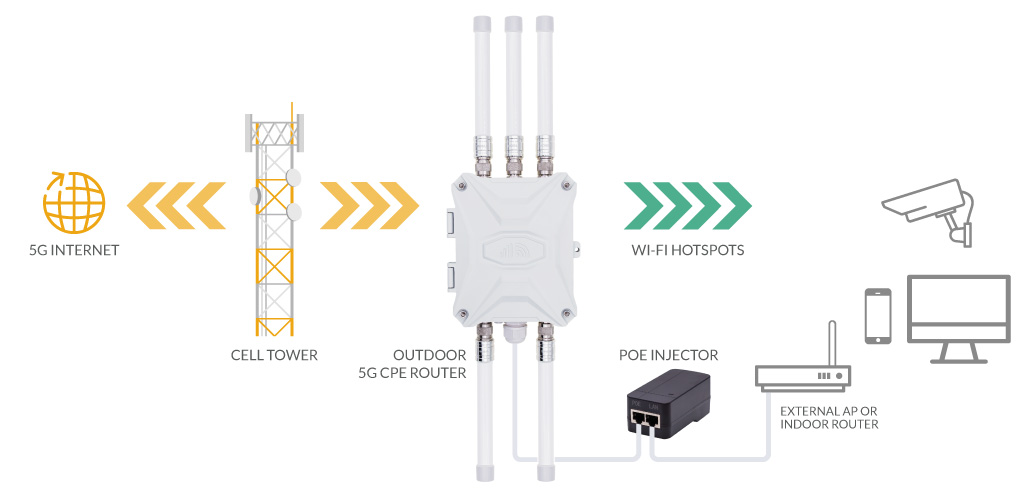


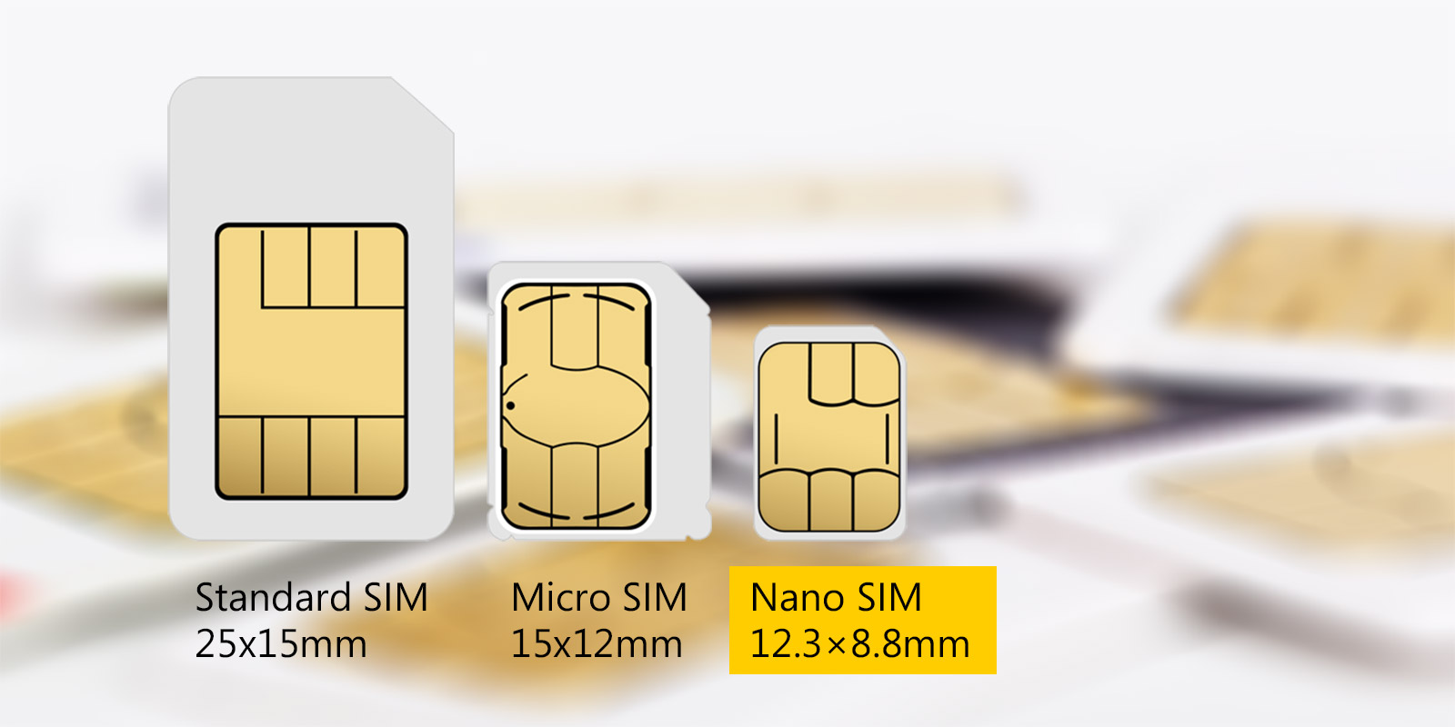 {% hint style="warning" %}
Please always **turn off the power** while inserting or removing the SIM card.\
Please use an unlocked and activated SIM card.
{% endhint %}
### **Insert A SIM Card**
1. Locate the SIM1-2 slots in the top right corner of the motherboard.
2. Hold the lid of the SIM card slot and slide left to open the cover.
3. Put a Nano SIM card in the **SIM1** slot. \
*There is only one correct way to settle the SIM card - the gold pins should be face down, and the notch should be on the top right corner.*
4. Cover the SIM lid and slide right to lock the lid.
{% hint style="warning" %}
Please always **turn off the power** while inserting or removing the SIM card.\
Please use an unlocked and activated SIM card.
{% endhint %}
### **Insert A SIM Card**
1. Locate the SIM1-2 slots in the top right corner of the motherboard.
2. Hold the lid of the SIM card slot and slide left to open the cover.
3. Put a Nano SIM card in the **SIM1** slot. \
*There is only one correct way to settle the SIM card - the gold pins should be face down, and the notch should be on the top right corner.*
4. Cover the SIM lid and slide right to lock the lid.
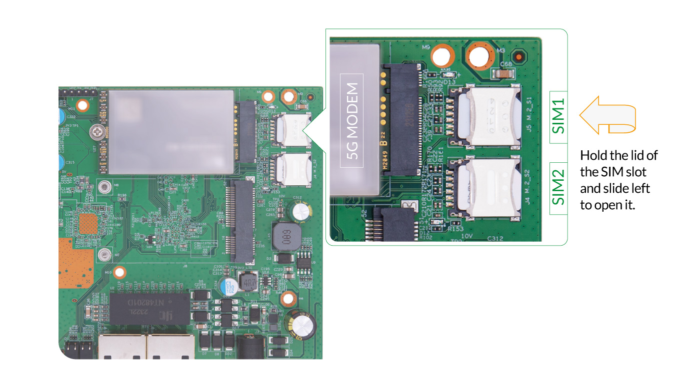


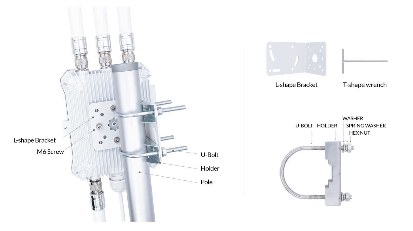
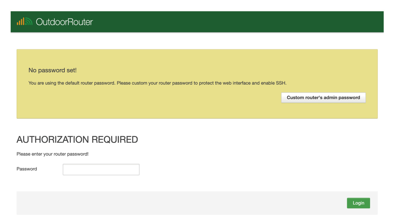

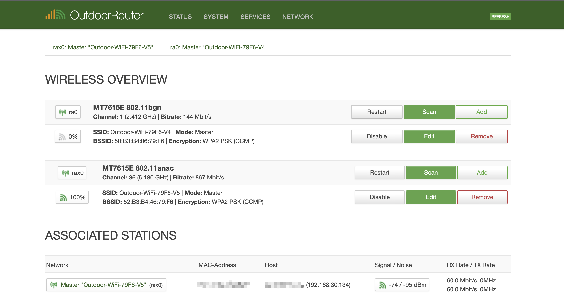
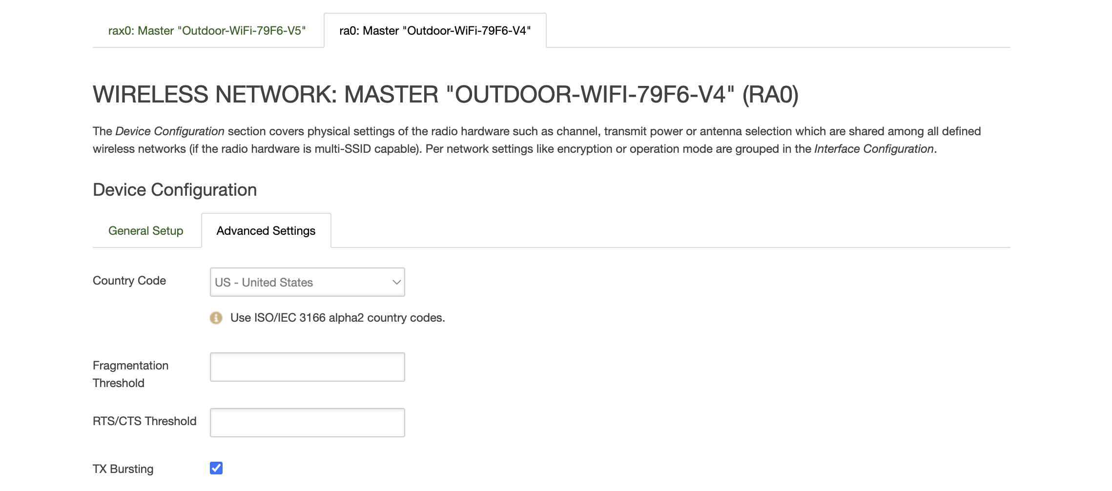
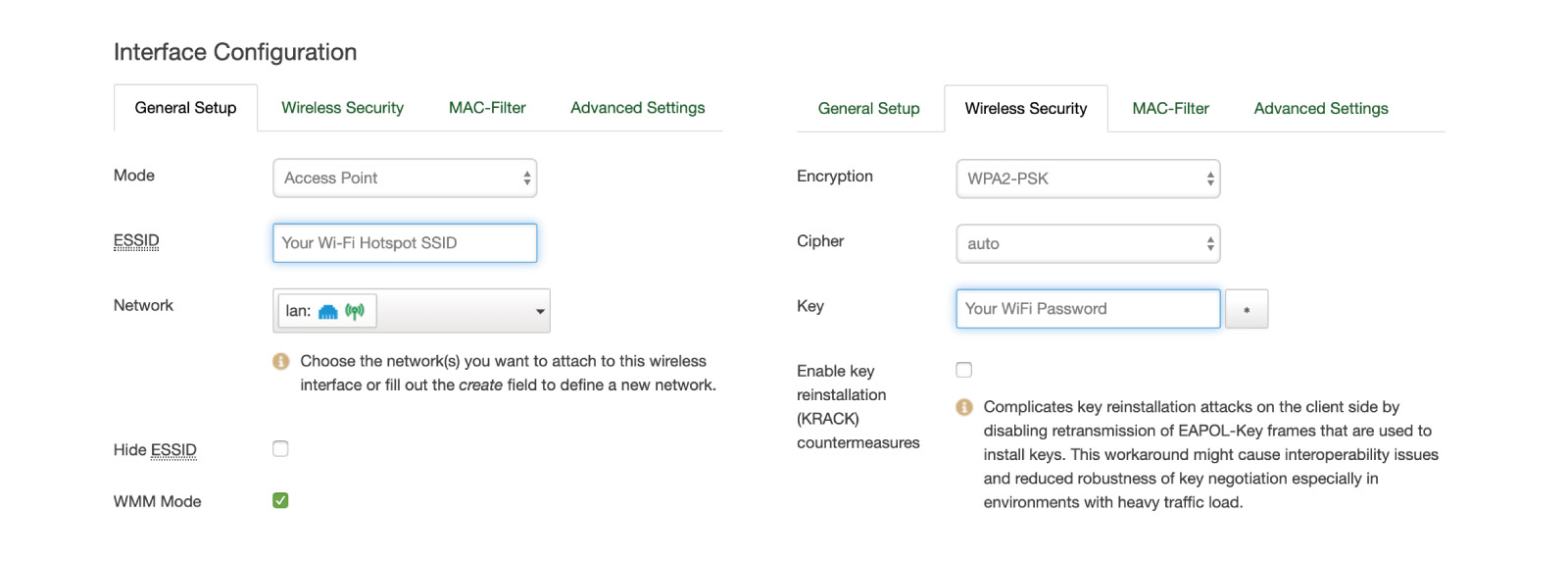
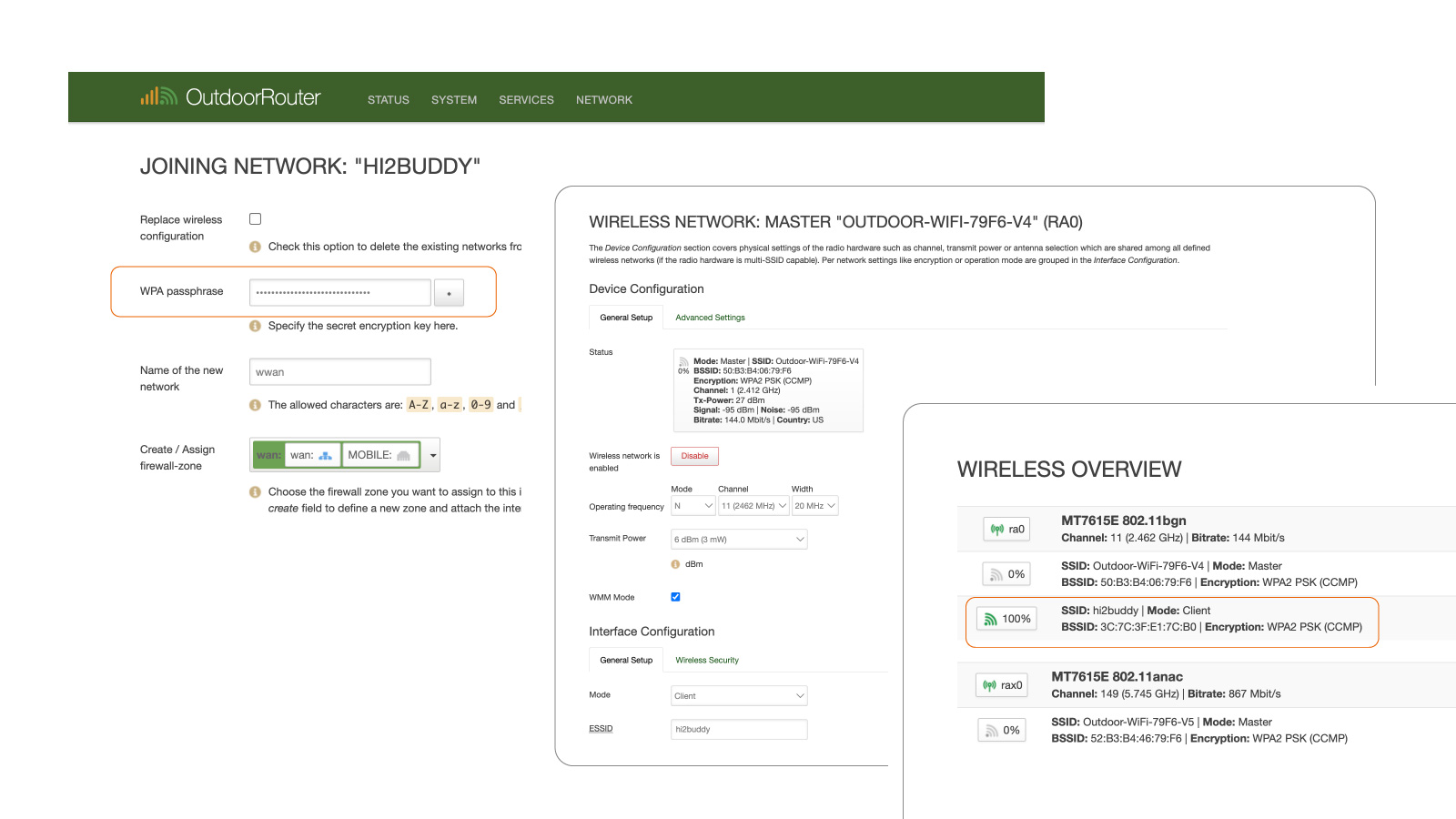


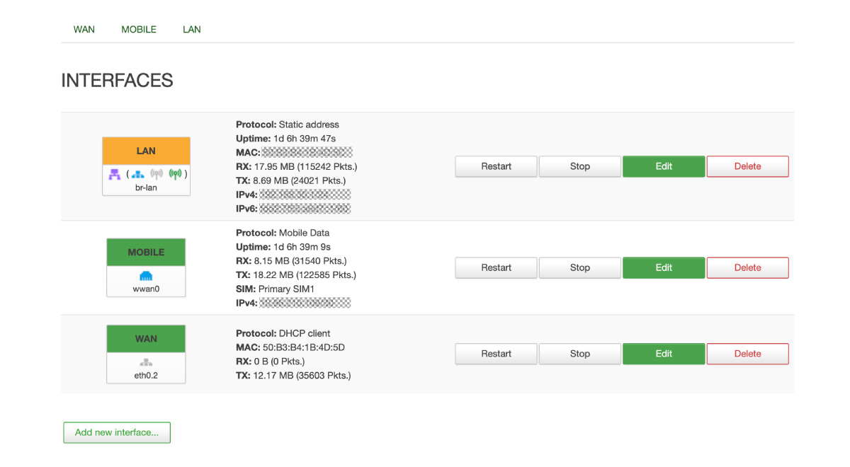
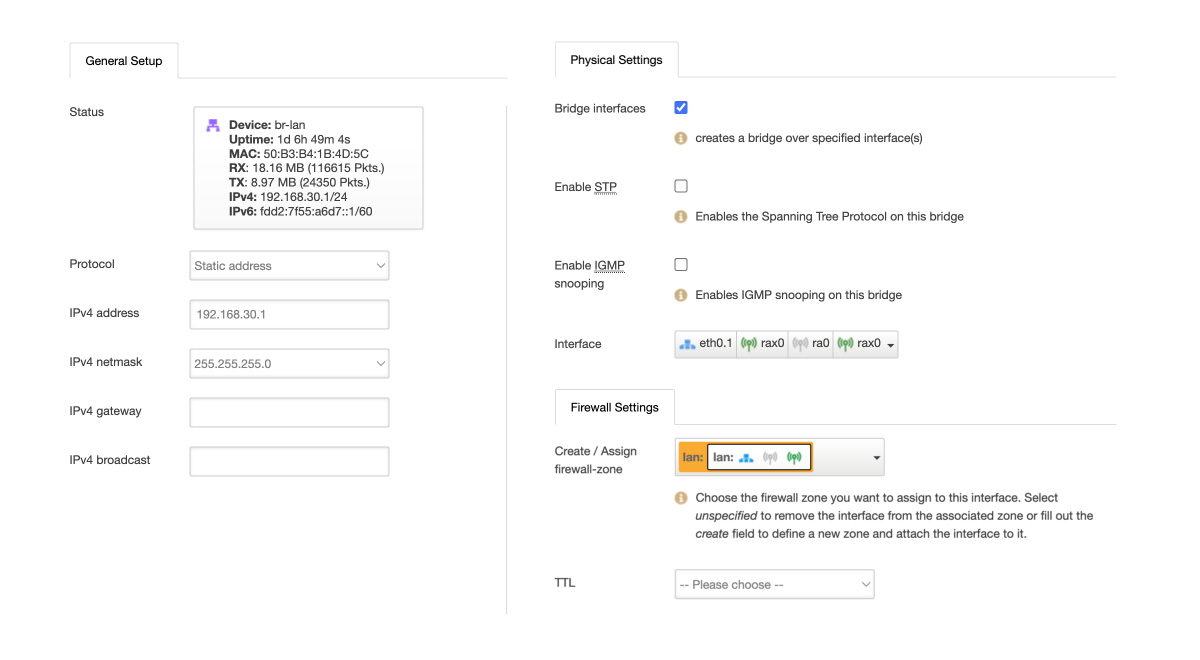
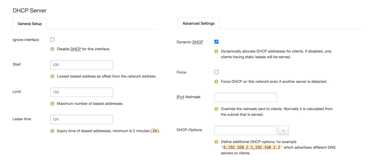
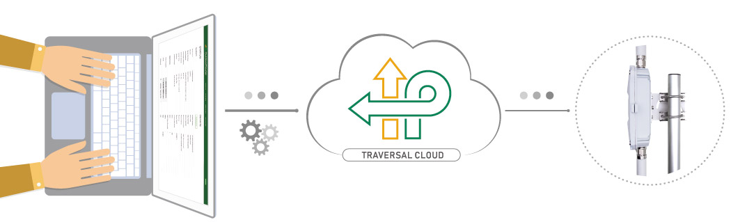


.png?alt=media&token=0f1e284d-8ee1-4b76-8888-e99b082ae21f)